
For those just joining, in the first 3 entries we introduced NSX overlay networking to a vCenter environment, performed all of the required base configuration, and created our first upper layer network service appliance, the NSX Edge. To review, the NSX Edge is a lot like the old vShield Edge in that it is a firewall appliance with NAT, firewall, load balancing, VPN termination, but very much unlike the original in that it is a massively capable router as well. In addition every one of those capability areas has been dramatically expanded since the vShield days. In short it is a full features virtual perimeter appliance that can stretch up to layer 7 as well as handle internal routing between (virtual) subnets (VXLAN vwires or, in NSX parlance, layer 2 domains on the logical switch) as well.
One of the most exciting things about a true overlay network like NSX, and why the Nicira acquisition was such a smart one by VMware, is that the virtual network constructs don’t just stop at the perimeter. It’s a really powerful thing having this truly virtual, software based router available as a click-to-deploy console. Some of the limits of the Edge, though, are that it is limited to 10 interfaces (just like vShield) and it also has a lot going on that is all perimeter based. What if you just want a pure router? Well the fantastic news here is NSX has you covered. The logical routing appliance is a subset of the NSX Edge, focused just on routing, that also adds the capability to be a bridge. This opens a huge range of possibilities. Before we get into those possibilities though, let’s get one up and running!
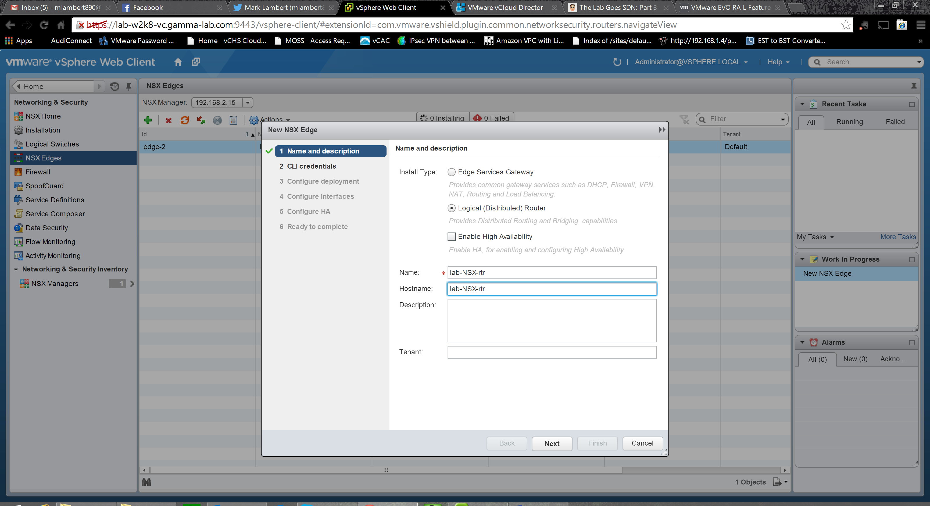
As always, head to the web client Networking & Security plugin. Select NSX Edges and click the green “+” to add. Last time we deployed an Edge Services Gateway, this time we’re doing a “Logical (Distributed) Router”. Once again we give it both a name (for the VM appliance) and hostname (for the actual OS) and have the option of enabling High Availability:
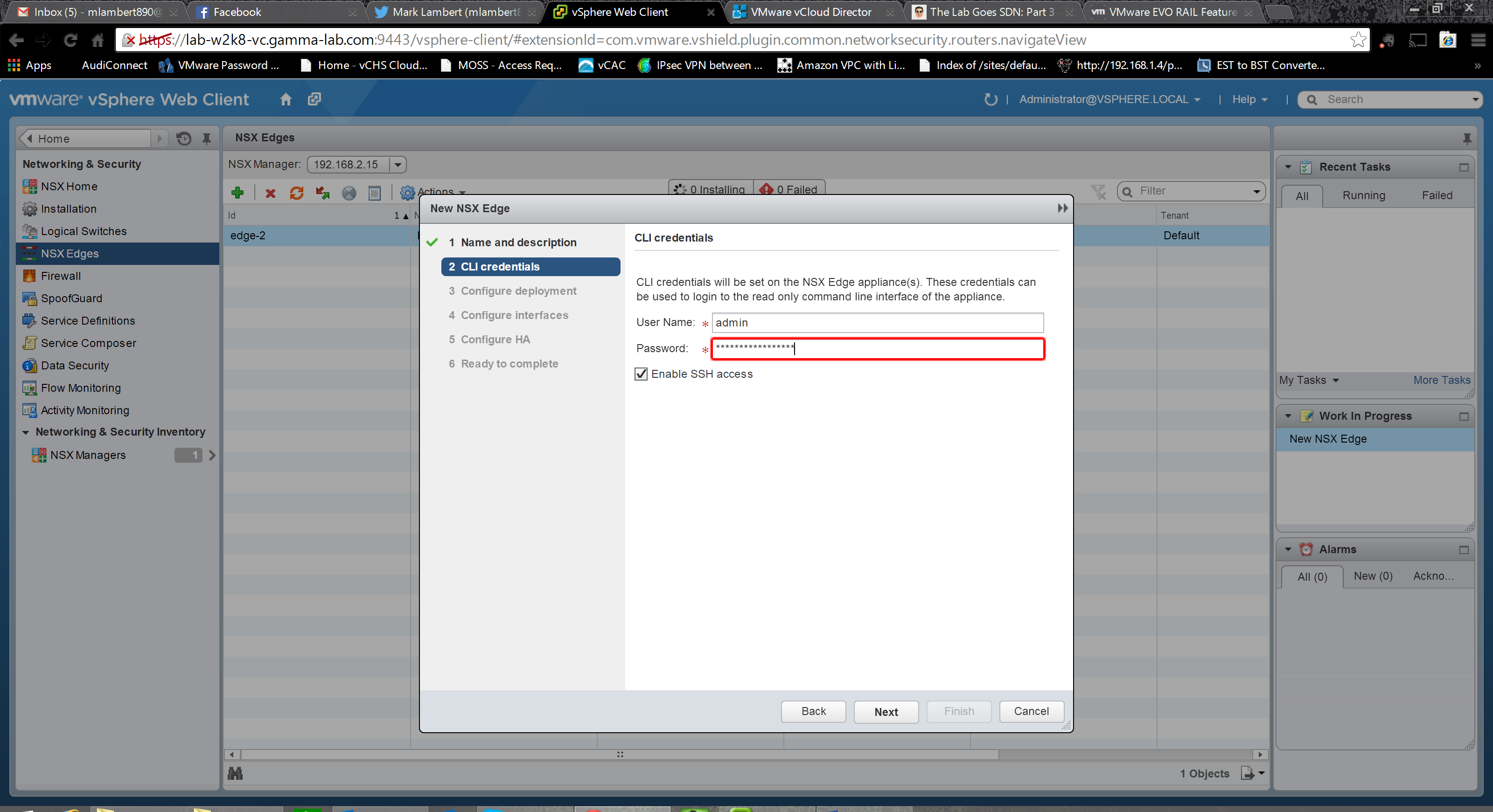
Next we enter a password. Once again, extremely strong password rules are enforced:
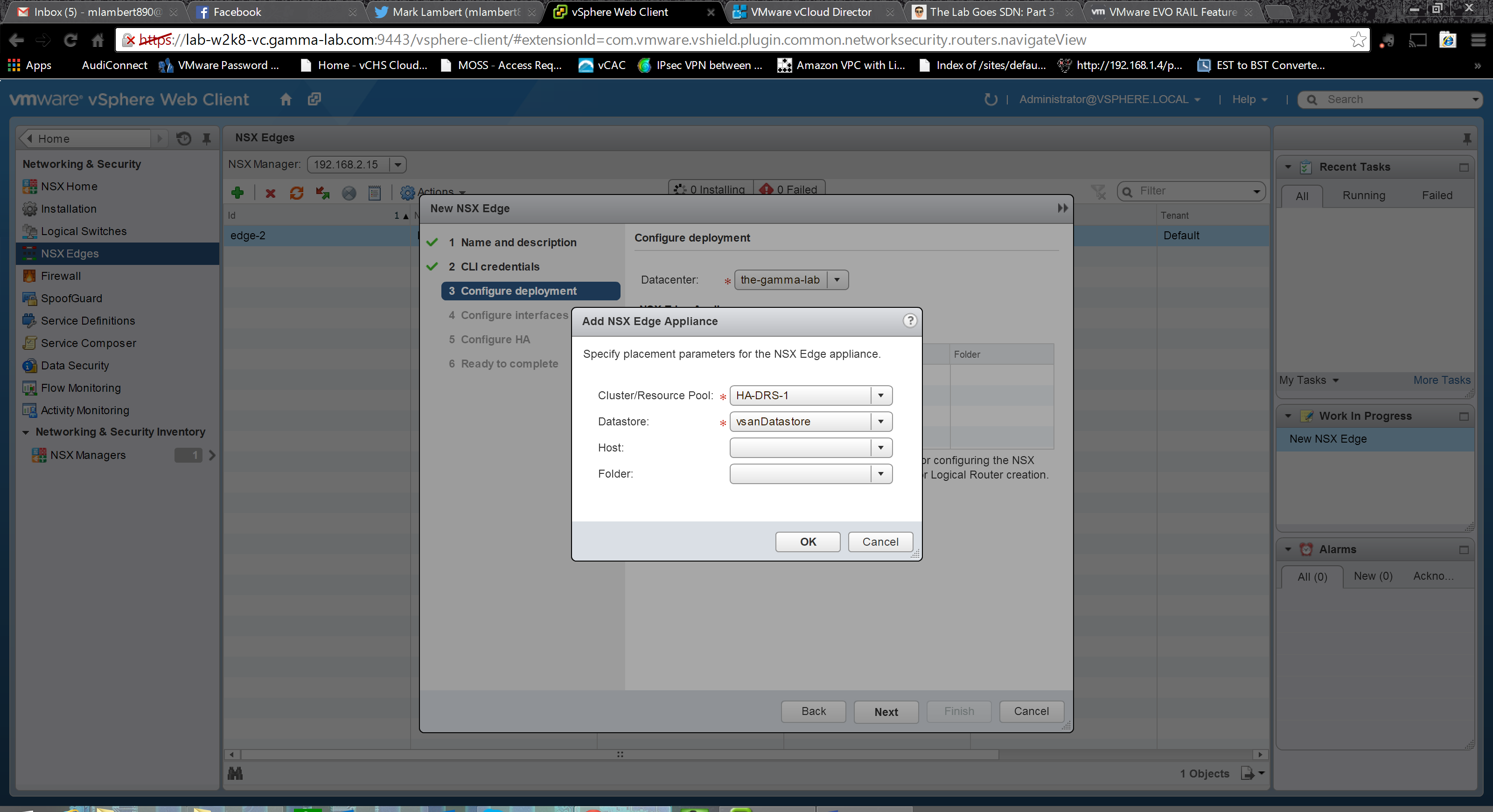
So far the wizard is identical Select a datastore to which the logical router appliance will be deployed. In my case once again sending it to the vSAN:
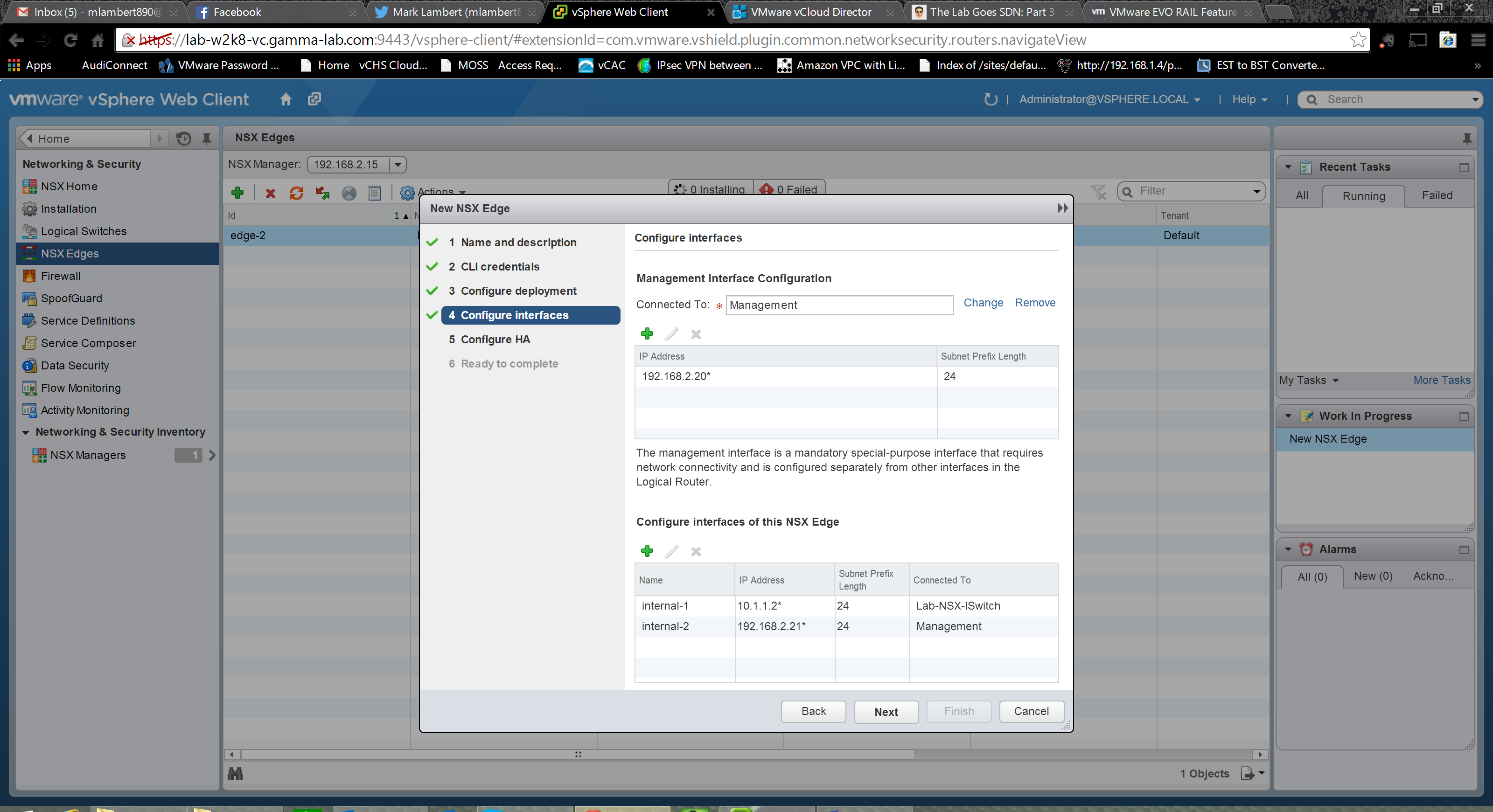
Next up is the interface configuration. Finally we diverge a bit from the NSX Edge wizard. For the logical router we need to configure a dedicated management interface (management plane) in addition to adding actual routing interfaces (control and data planes). For the management interface I’ve created a port group on the vDS which shares a VLAN with my physical hosts vSS since this is where all of my base VMs reside (vCenter, vCS, etc). After connecting the management interface to a port group add a valid IP:

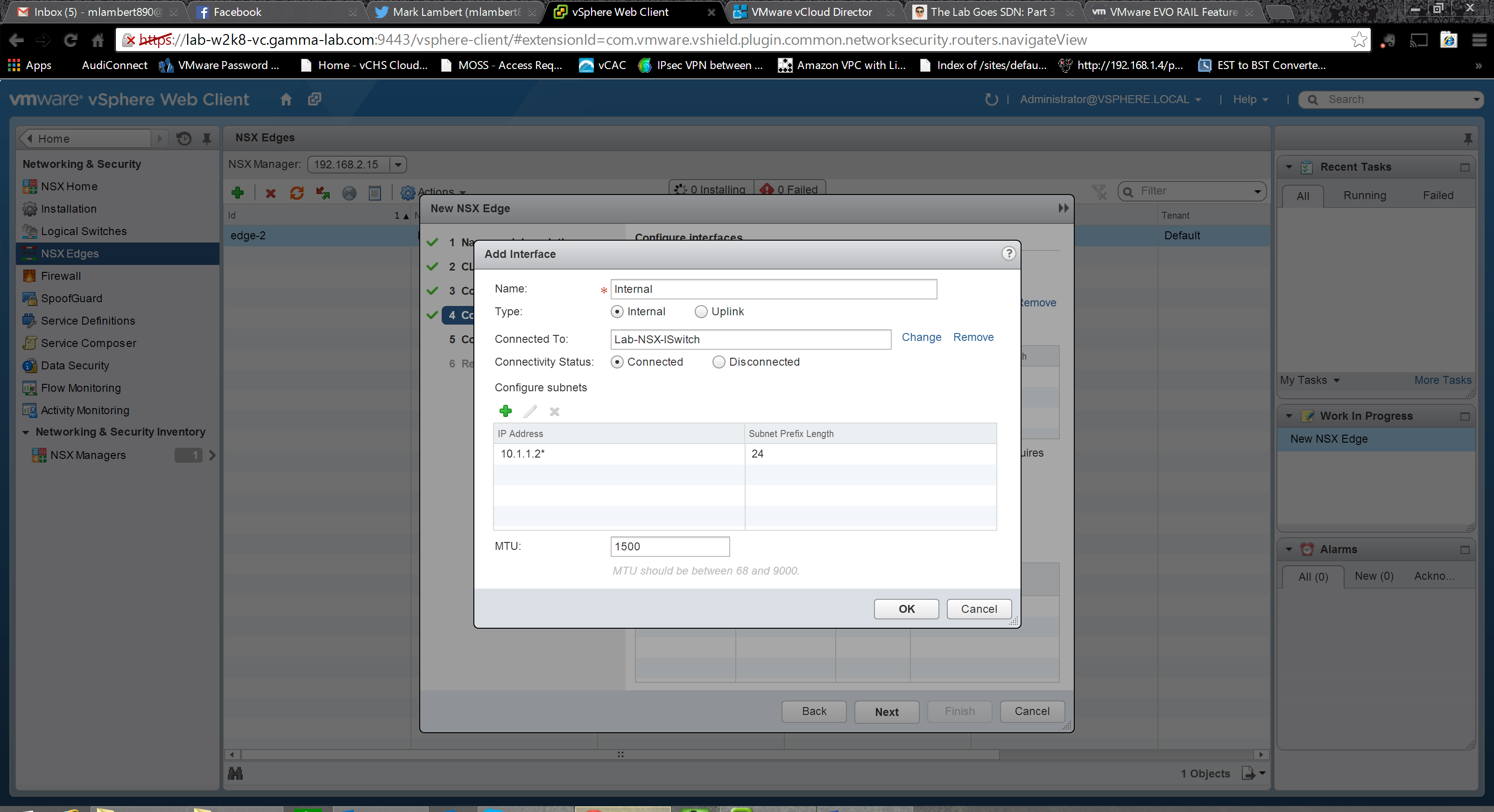
With the management interface configured, we’re back to business as usual. Here we are adding the routing interfaces exactly the same as we did on the Edge. Name them and classify them as either internal or uplink, then connect them to an appropriate port group. It is important to note that interfaces on the logical router require VLAN tagging in order to connect. That is worth repeating. If you create an interface on the logical router, and connect it to a port group which is set to VLAN0, it will allow you to do this and deployment will fail. Not quite sure why this is, or why it isn’t a pre-requisite on the Edge, but it is something to be aware of for the logical router. Once again, add IPs for any created interfaces and adjust the MTU as needed:
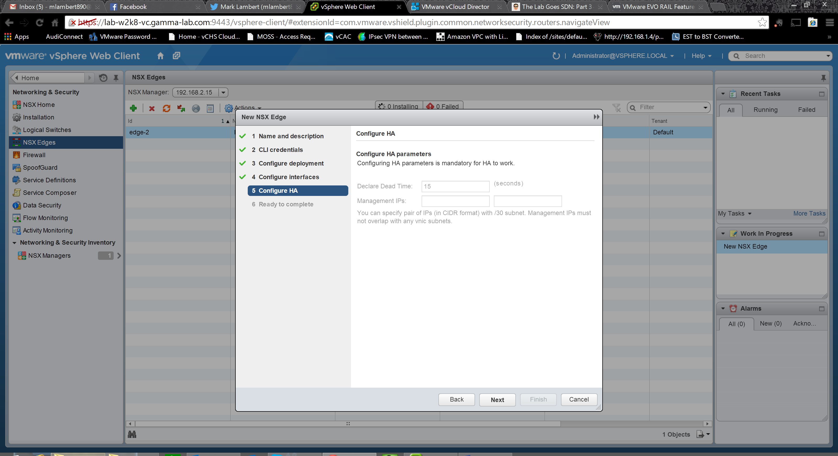
If HA was selected we configure it once interface configuration is complete:
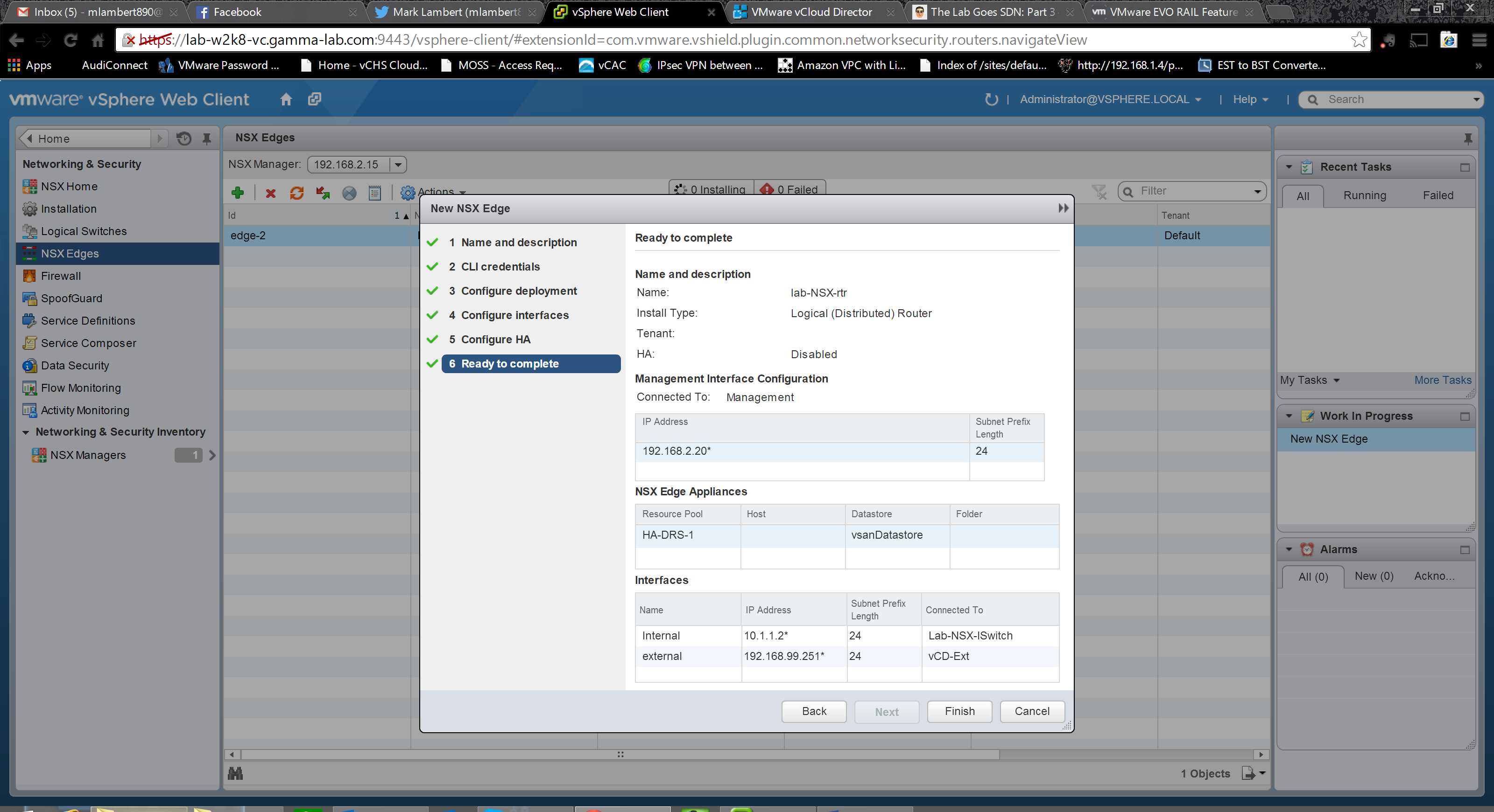
One final check before deploying to verify that everything is correct:
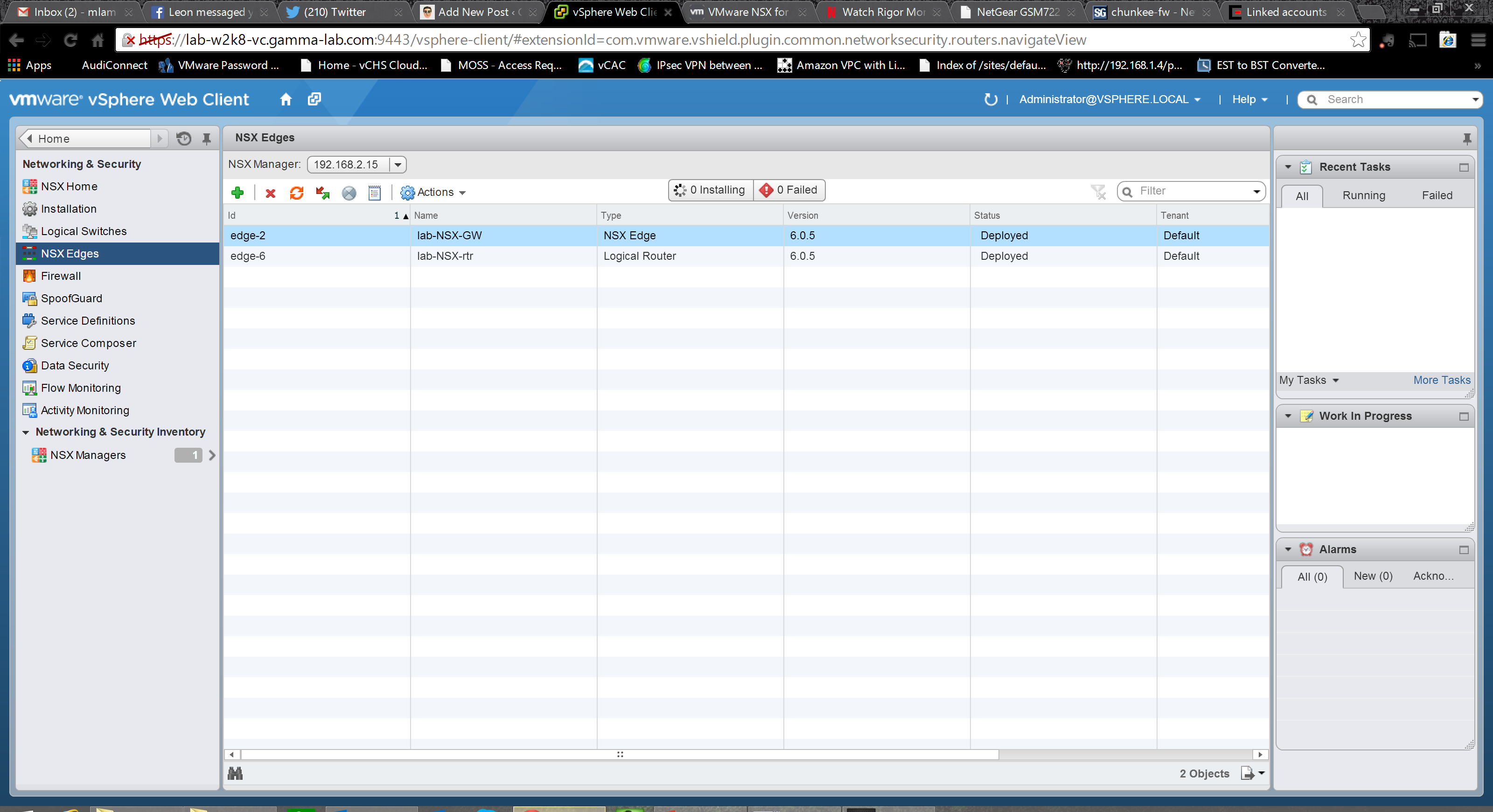
And viola! As long as resources are available to host the appliance, and VLAN tagging has been set in the connected port groups, the logical router will quickly deploy:
Our router has been deployed, but we haven’t done any configuration. Double click on the router name to switch to the logical router configuration pages and be prepared for a treat. This is a seriously powerful virtual network element! On the manage tab we are confronted with a whole boatload of options. The first section, “Settings”, gives us a Configuration overview first. Here we can change the management interface config, as well as the HA parameters. We can also setup syslog anddownload logs for tech support troubleshooting. We can also deploy additional logical routers in the bottom pane:

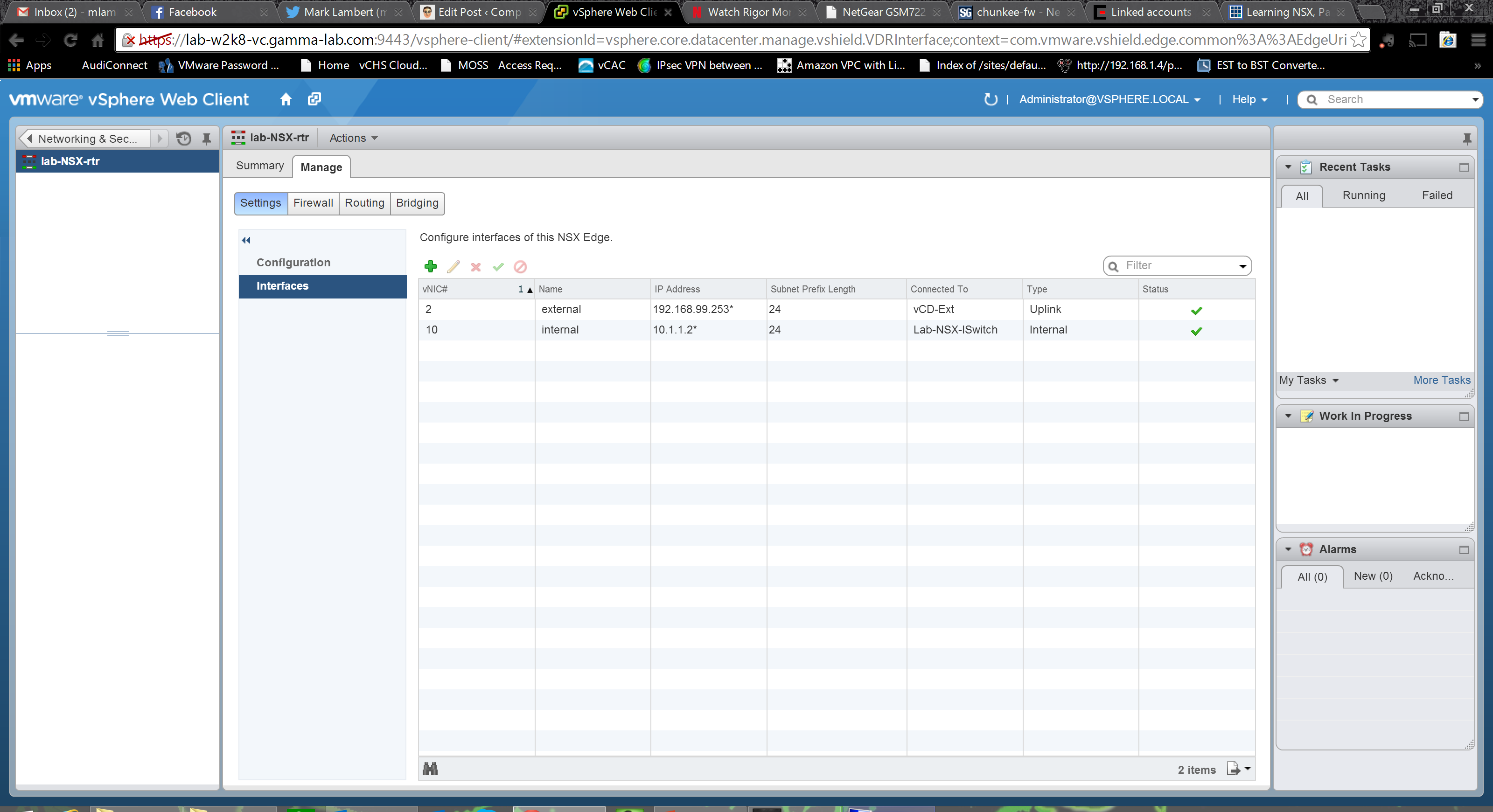
Under interfaces we can see the interfaces created during initial deployment. We can also add more using the same UI. A staggering 999 interfaces, with 8 of them being uplinks, can be created! Of course bandwidth of the underlying host should be scaled appropriately for the uplinks:
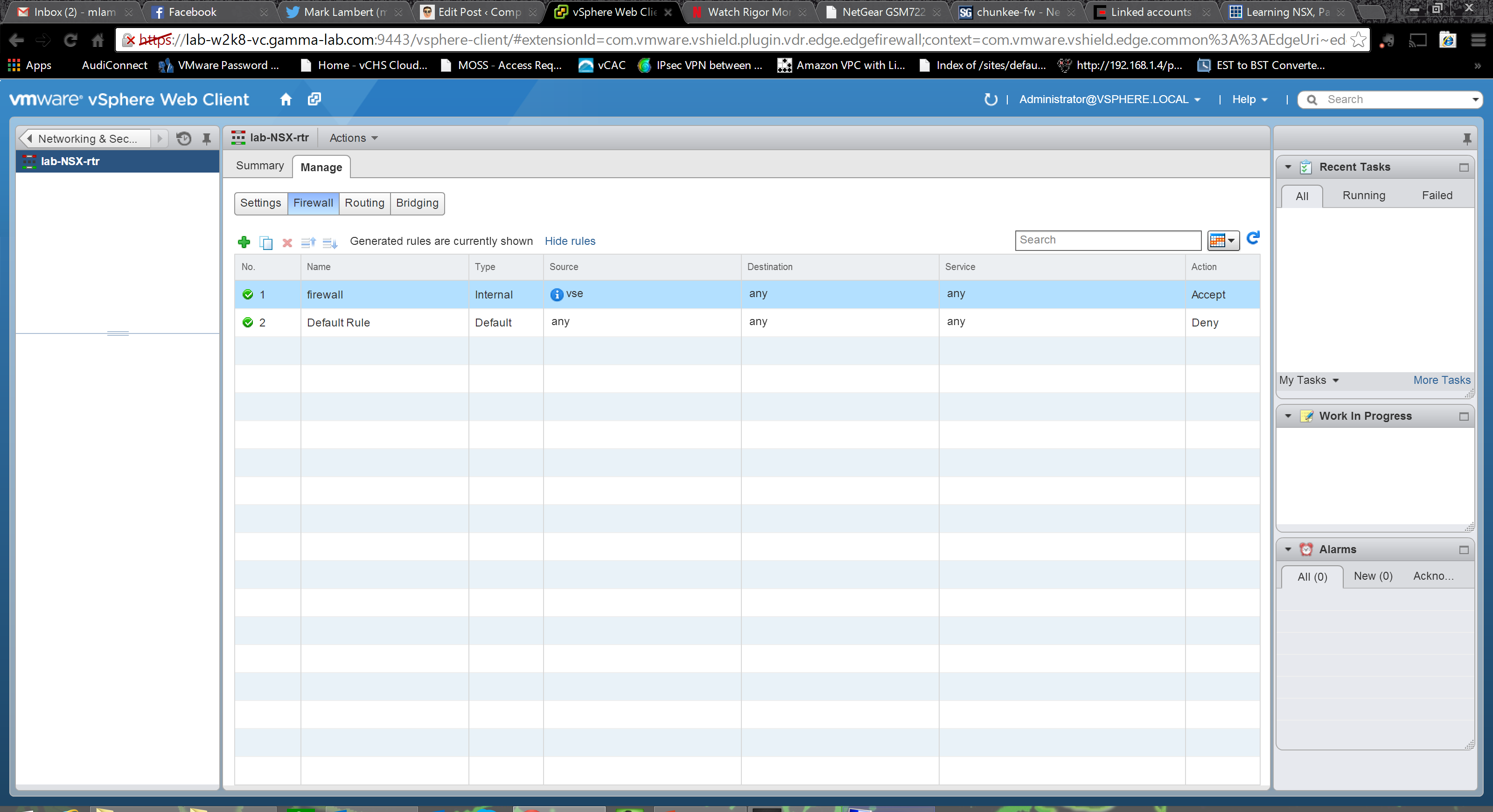
The Firewall section provides a really easy to use UI for creating ingress and egress filters. Very intuitive: name, source, destination, service, permit/deny:
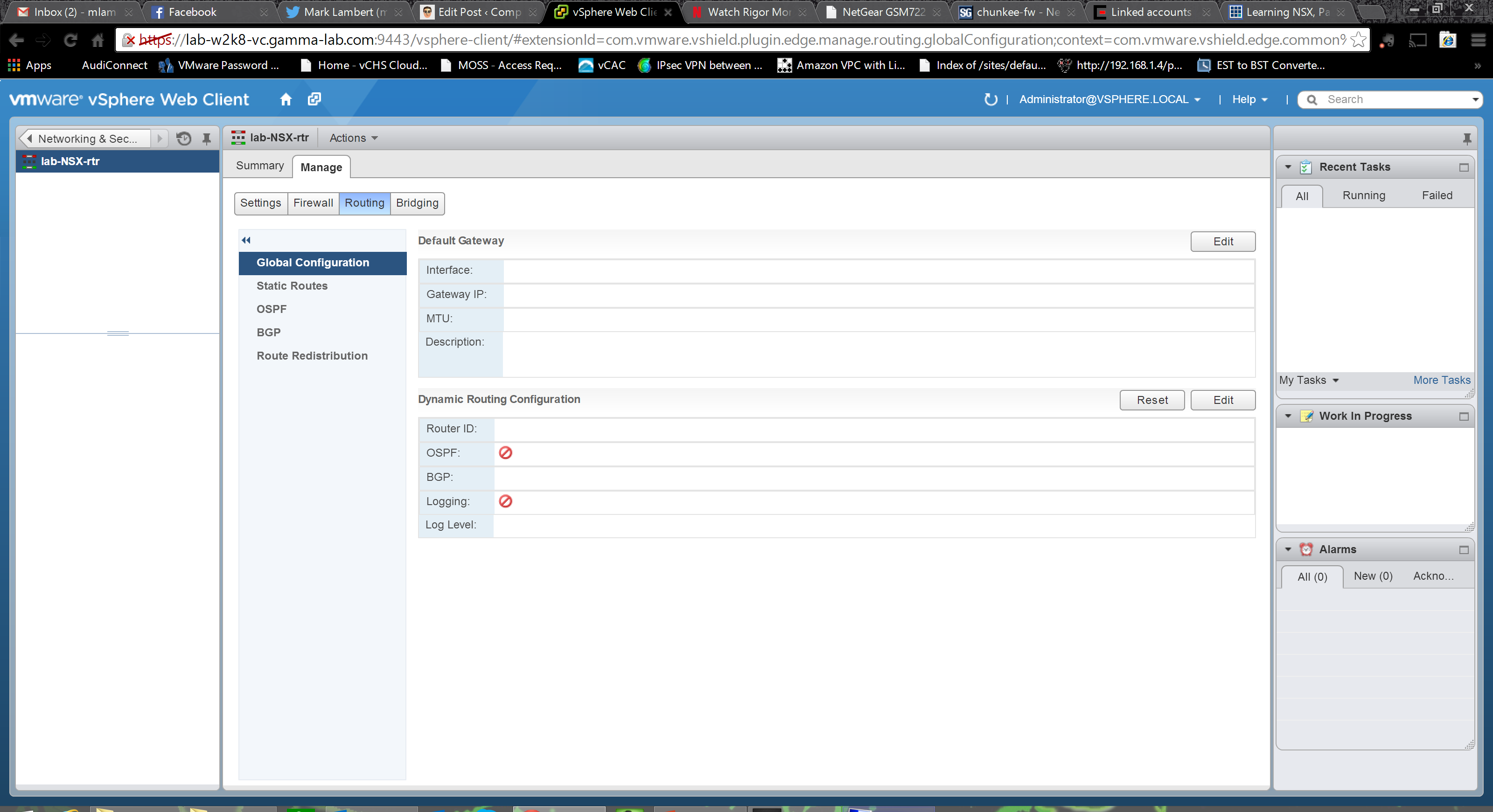
The Routing section is where things get really interesting and the true power of the logical router is unlocked. It starts off with top level configuration. Set a default gateway for the router itself, if appropriate, and then enable the dynamic routing options. OSPF and even BGP(!) are supported. This is fantastic as, with these two protocols, 80% of both internal and external integration cases are covered. We can also configure logging in this section:
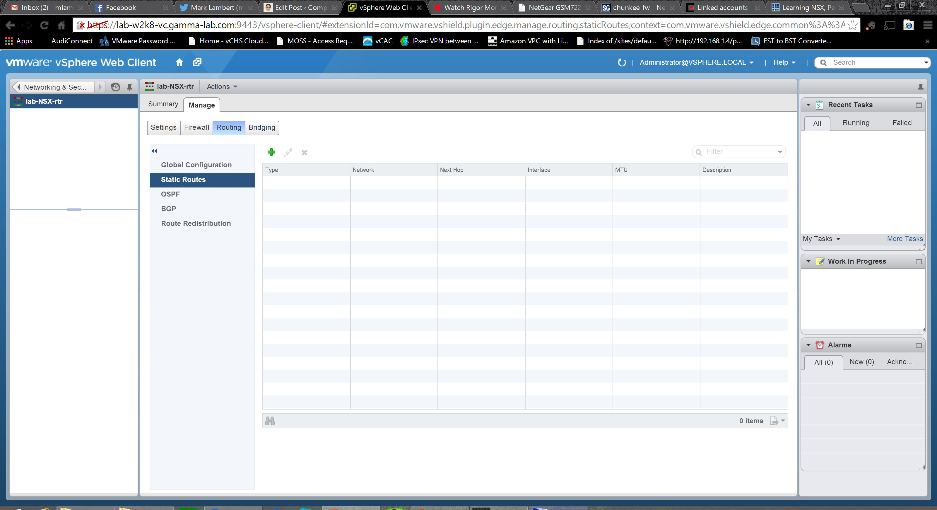
In the event that the logical router is being deployed into an environment without dynamic routing, static routes can be created. Once again intuitive, Interface, network, next hop, MTU (powerful – per route MTU, this is fantastic), and of course a description field:
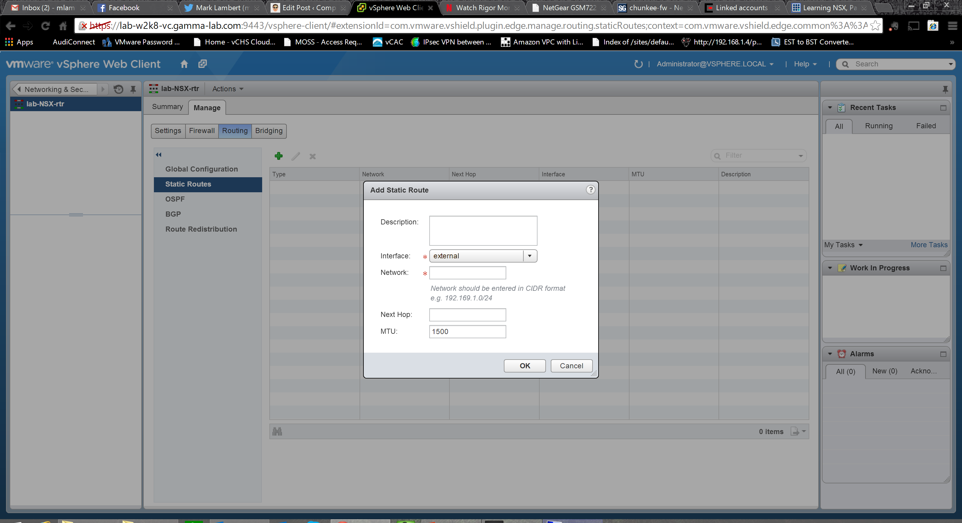
The static route dialogue is straight to the point:
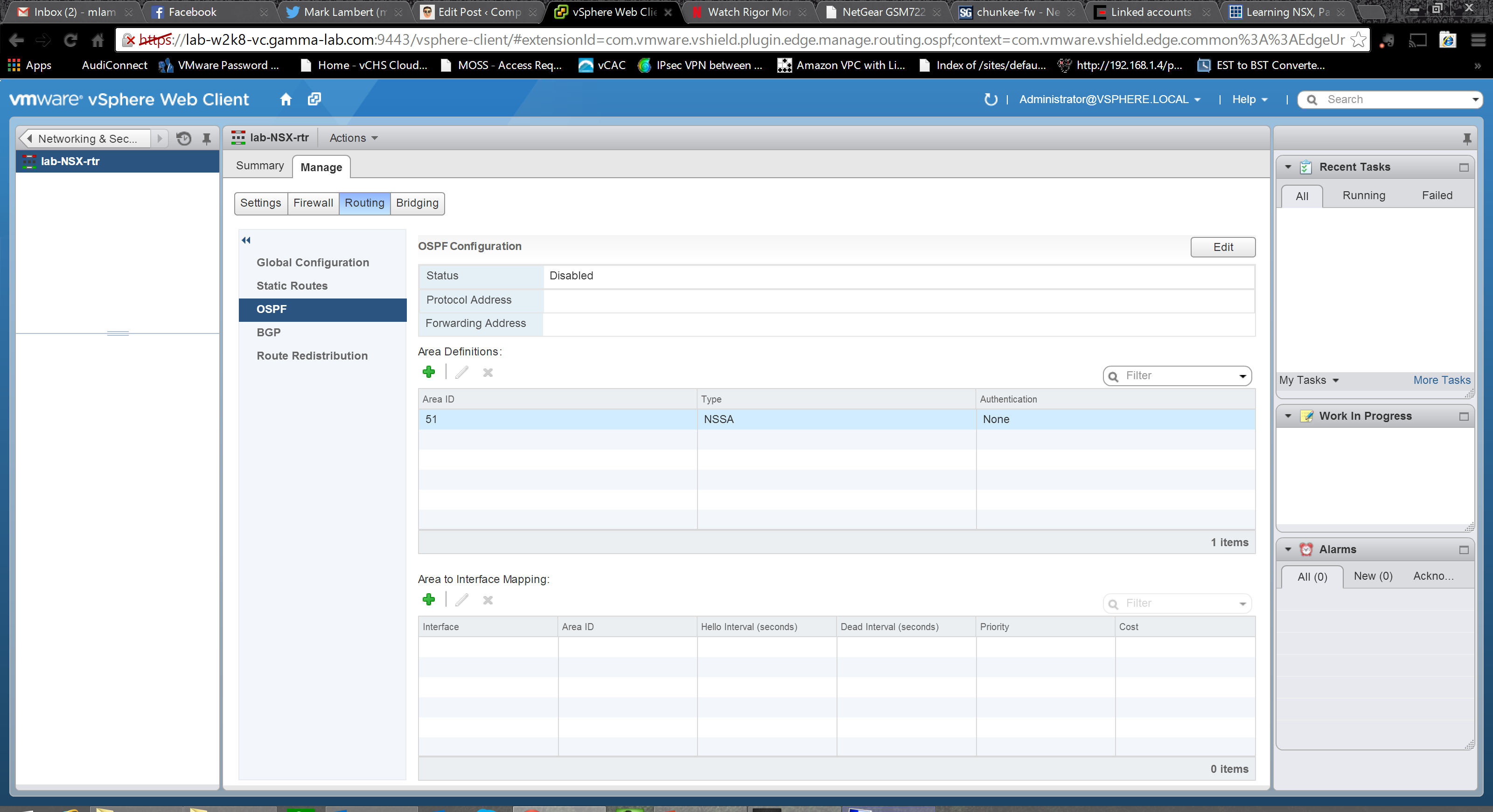
The OSPF tab is a bit overwhelming for anyone not familiar with the protocol, but will look like home to anyone who is. The fundamentals needed to get the logical router working in an OSPF area are here: protocol and forwarding addresses, definition of the OSPF area, and mapping of the area to an interface:
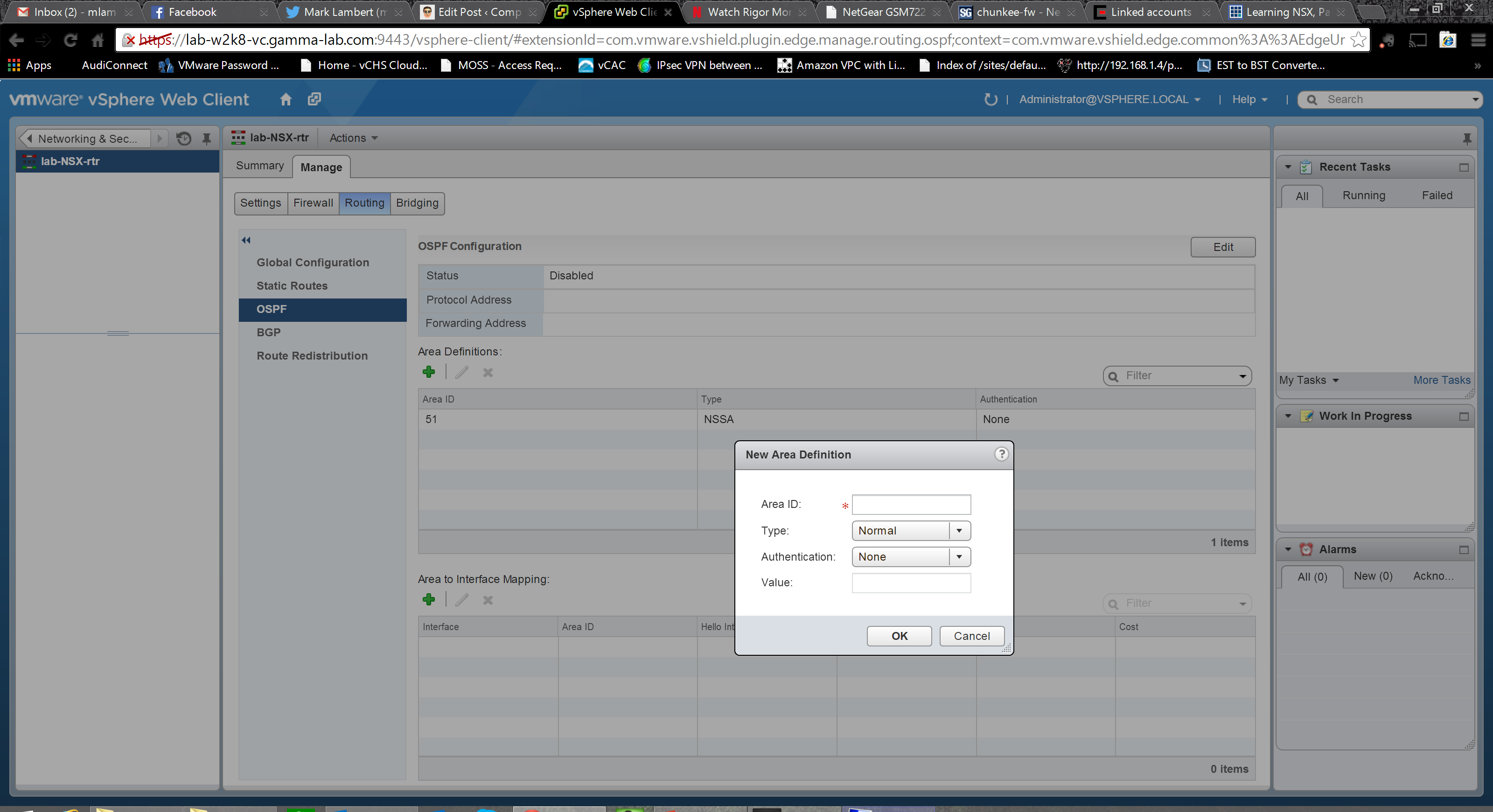
Adding an area we enter an ID, select a type (normal or NSSA – RFC 1587 “not so stubby area” for redistributing external BGP routes into OSPF) and an authentication method (MD5, password or none) as well as the authentication value (password or MD5 hash):
Once the Area is setup, we map it to an interface. Option here to ignore the interface MTU as well as advanced options to control protocol intervals, and set both priority and cost:

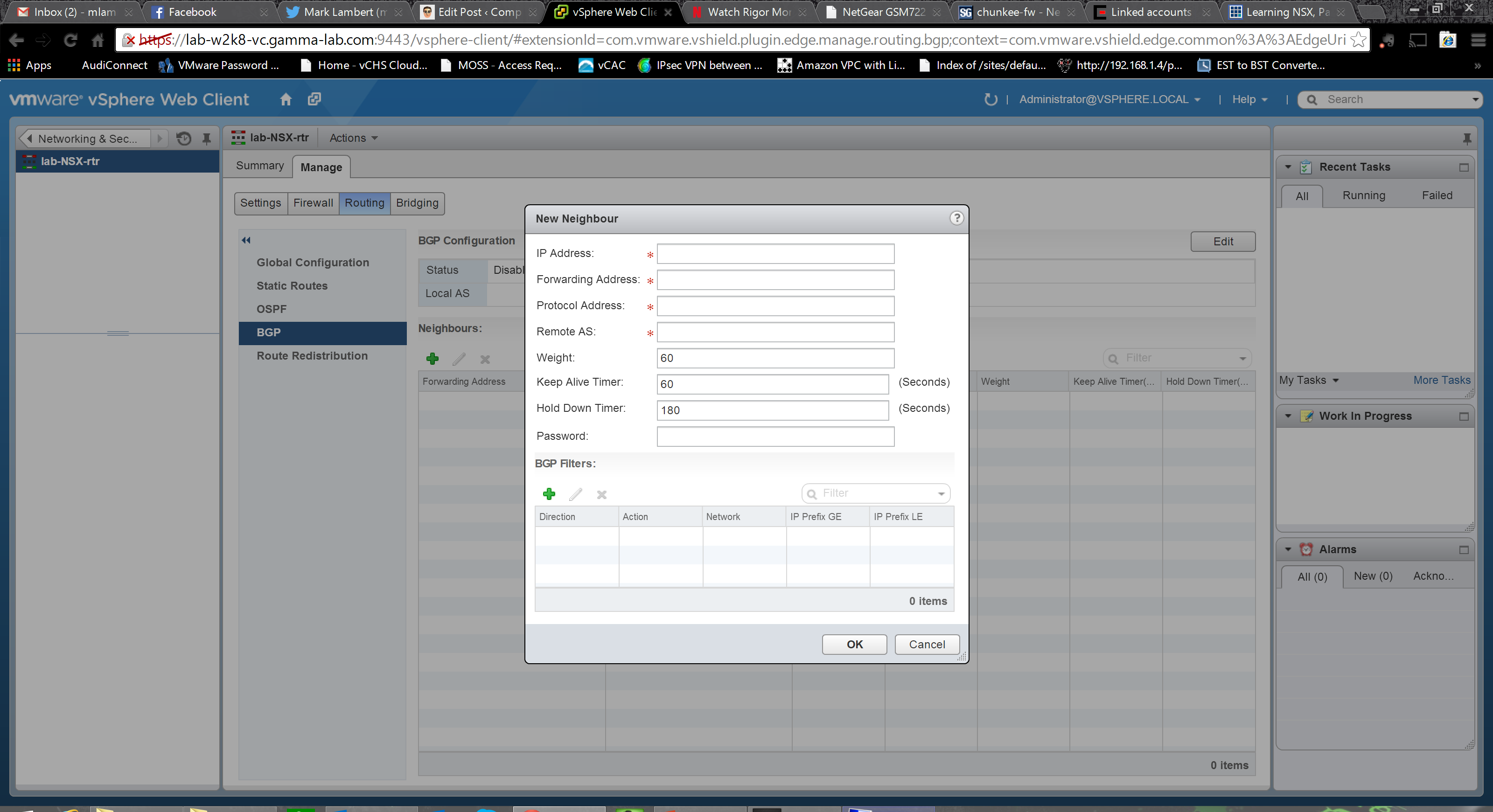
OSPF has our internal needs covered, so let’s move on to BGP to cover our external inter-org routing requirements. Once again, if you know BGP this is familiar territory. Up top we enable the protocol and assign our AS (Autonomous System Number – the identifier by which BGP peers identify each other and associate IP ranges with an endpoint). We also add our Neighbors – BGP peers with whom we are establishing a BGP routing relationship:

Peer configuration requires knowing a bit about your neighbor obviously. The remote organizations AS number is of course the starting point along with assigned IP address, as well as protocol and forwarding IP addresses. We can also enter timings and weightings and assign mutual authentication password. Once the foundation has been laid, we can also optionally add BGP filters:
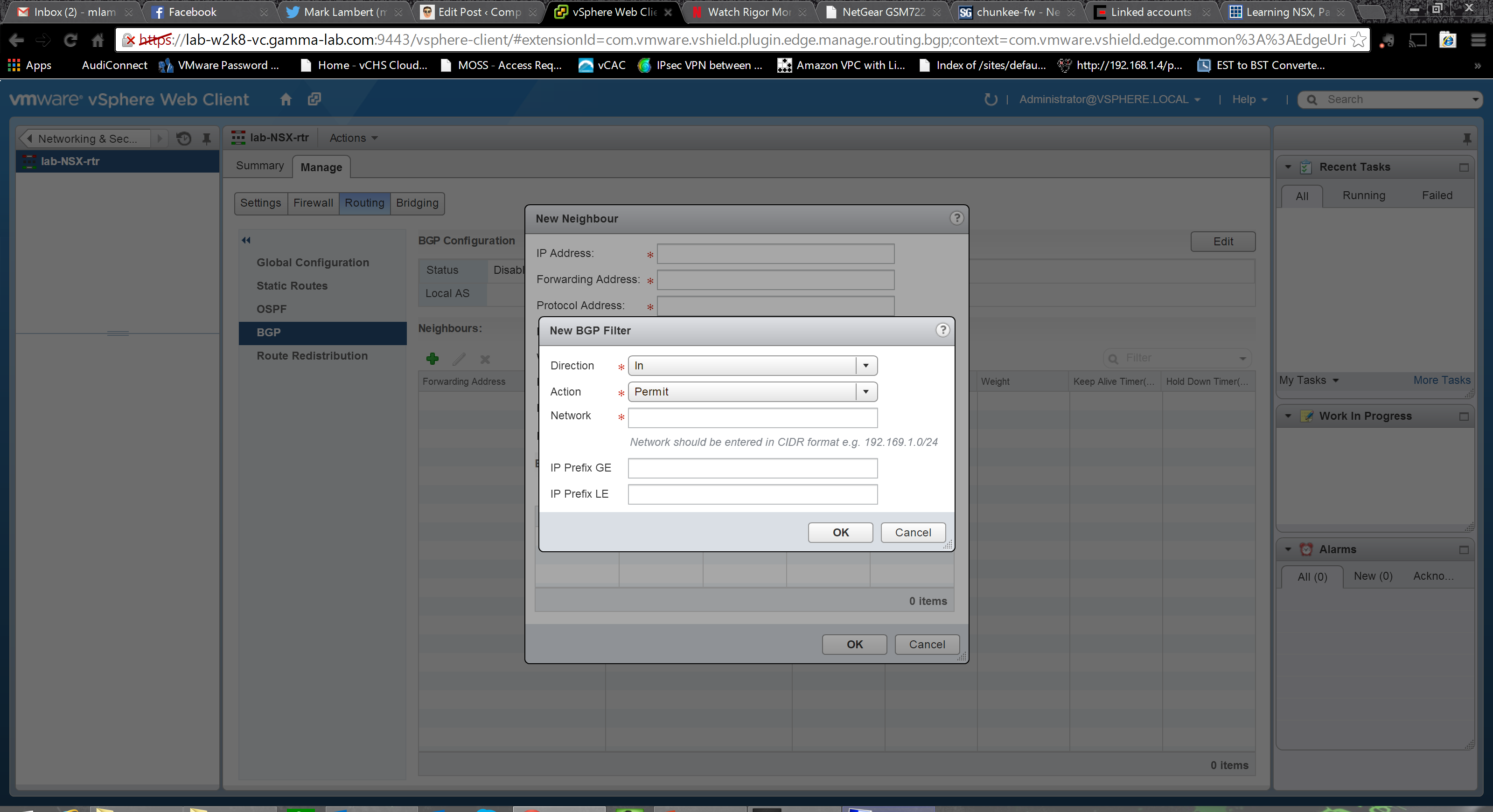
Adding a filter we set a direction (ingress or egress) and an action (permit/deny) on a specific network expressed in CIDR block format. We can also use IP prefix conditionals (GE – greater than or equal to, LE – less than or equal to) to apply to a range:
We’ve got internal routing. We’ve got external routing. Let’s link em! The Route Redistribution tab let’s us do just that:
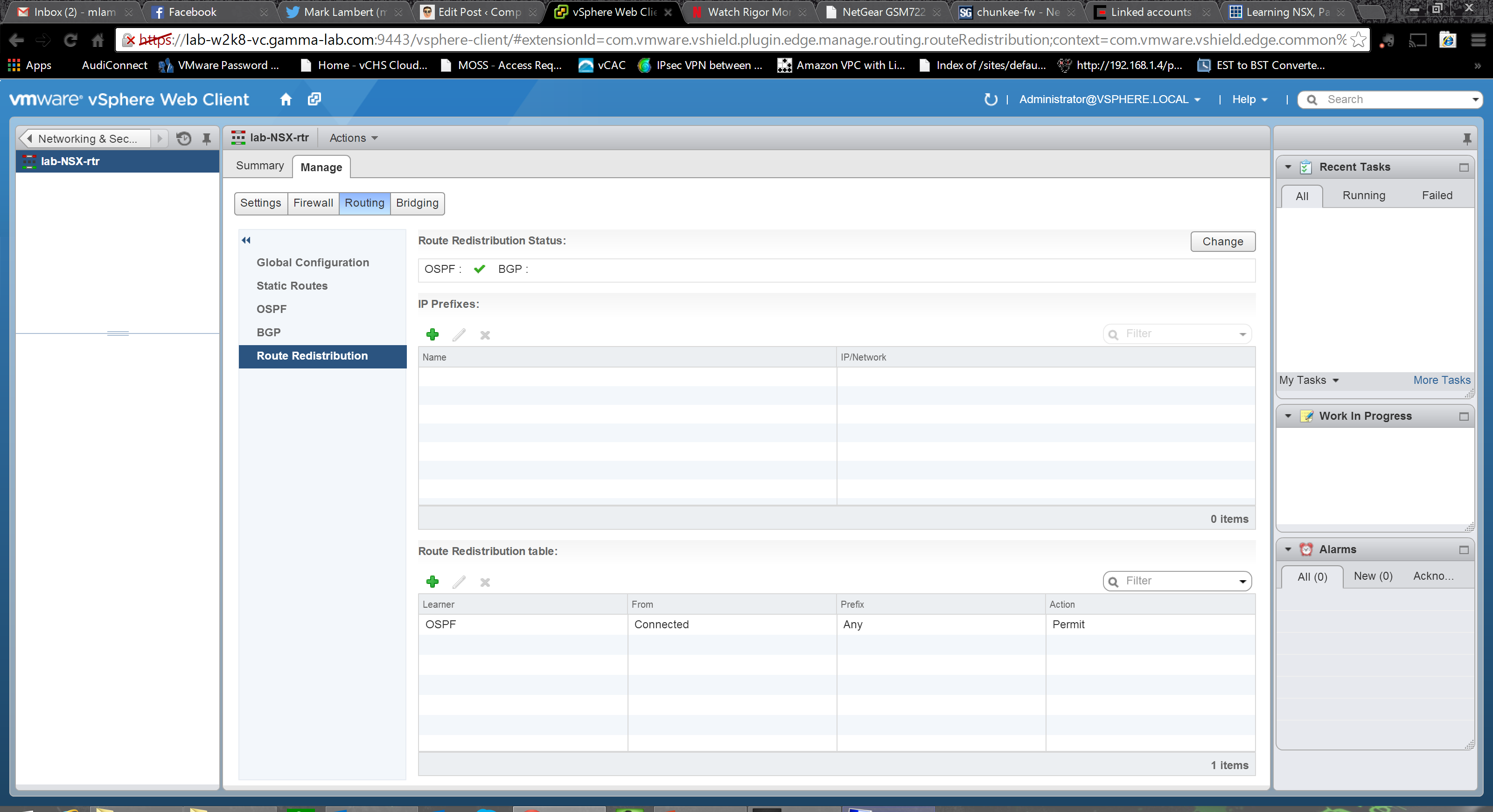
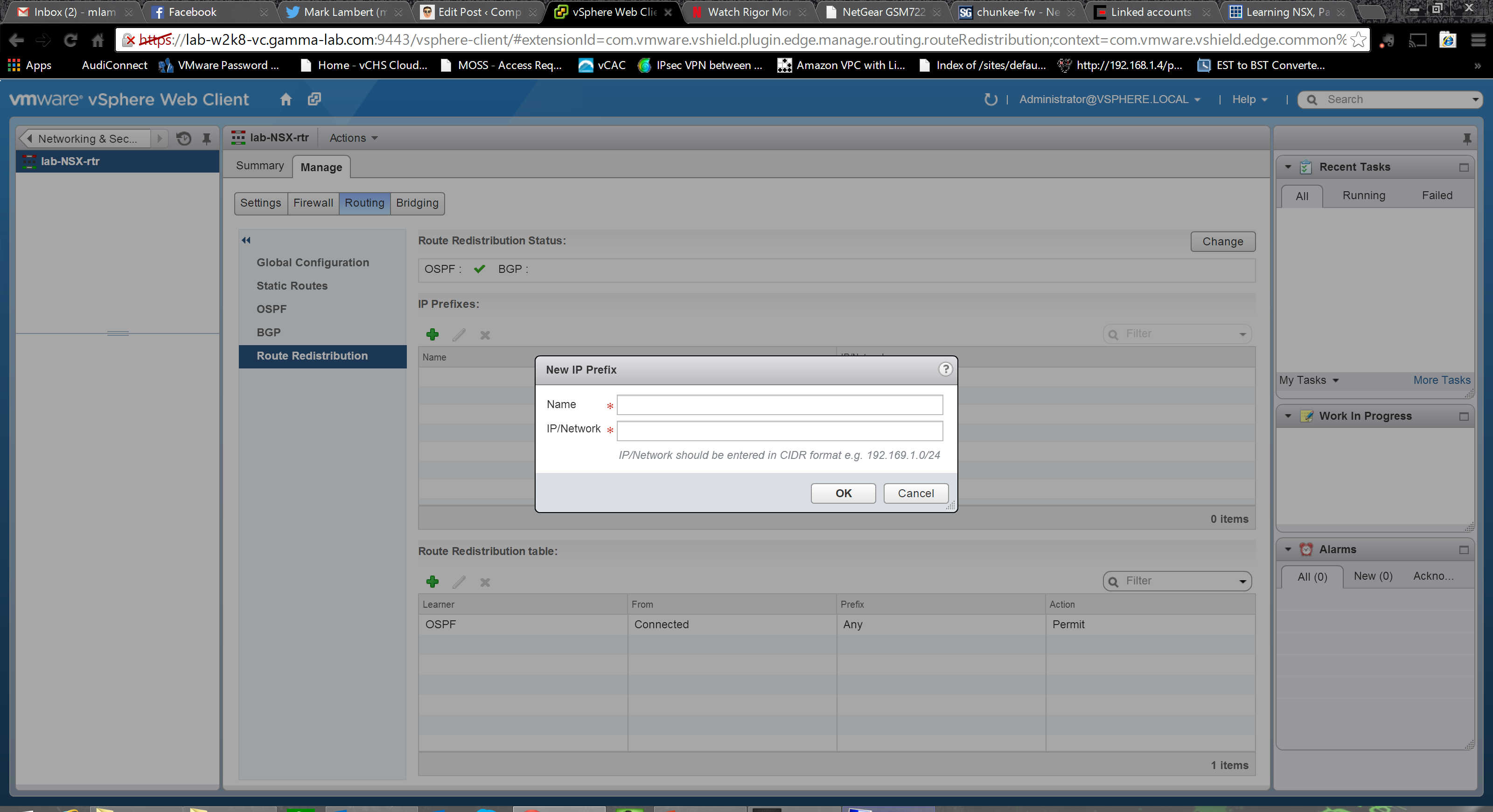
First we establish the IP prefixes for route redistribution. Name and CIDR notion network definition:
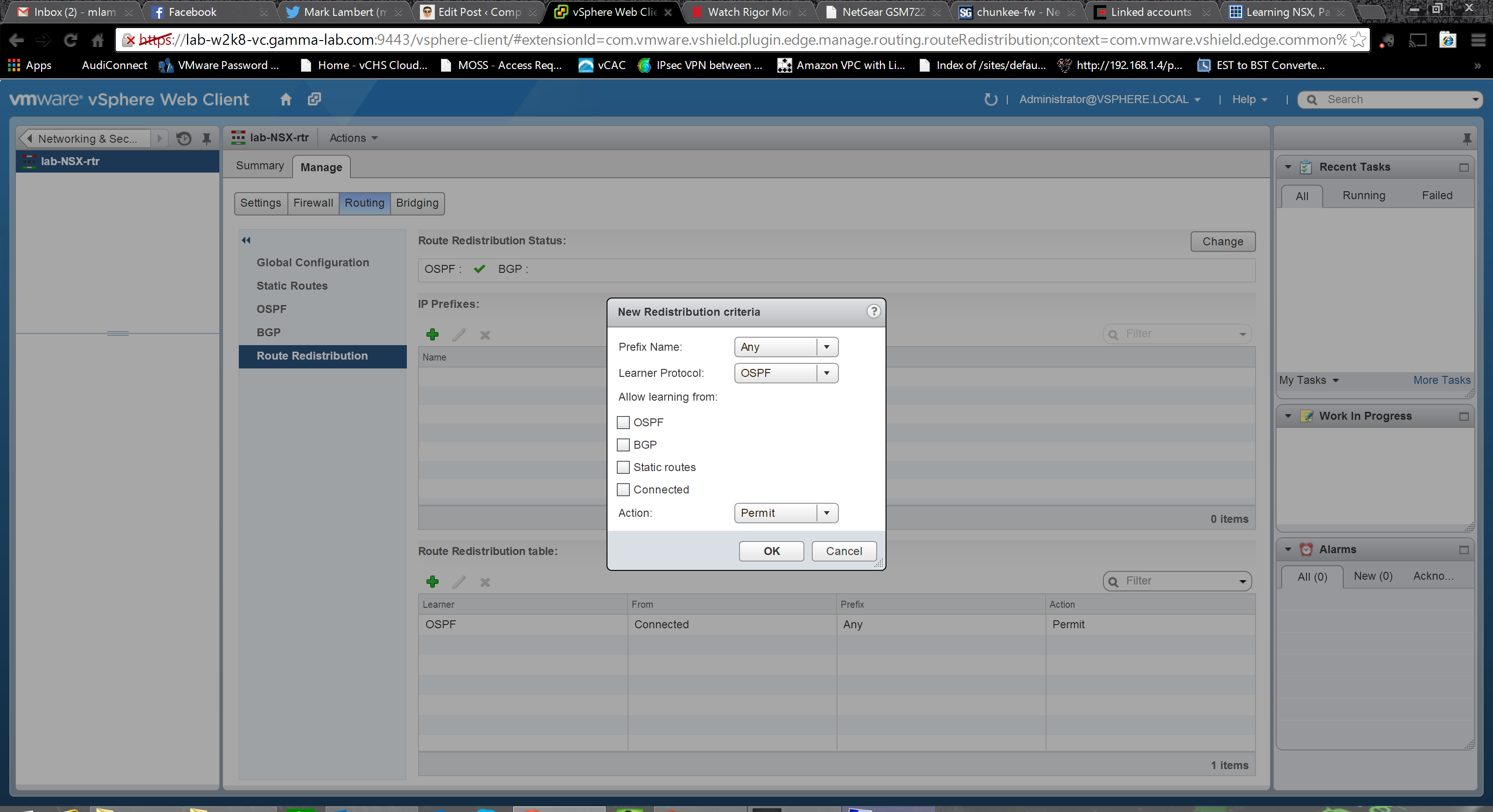
Next we create the redistribution criteria. Select the prefix (network defined above) and then set direction. The “learner” protocol is where the route is being distributed, the “learning from” entry is where the route is originating. Origination can be OSPF, BGP, static or directly connected networks. Destination can be OSPF or BGP:
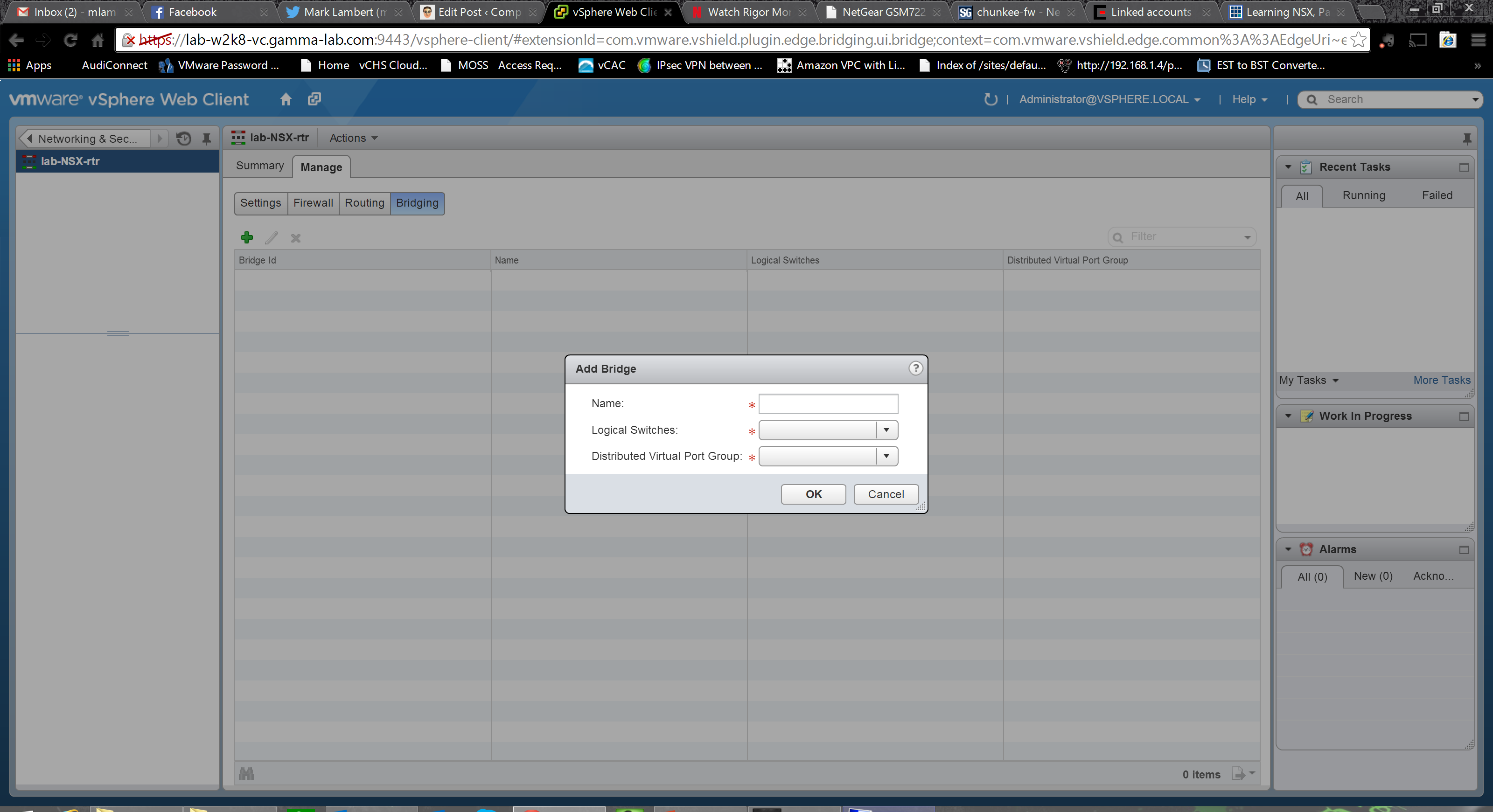
Last but not least we have bridging. Yes, this appliance can be a proper Ethernet bridge as well giving us fantastic layer 2 options for scenarios that need them. First step on the bridging tab is to add a bridge configuration:
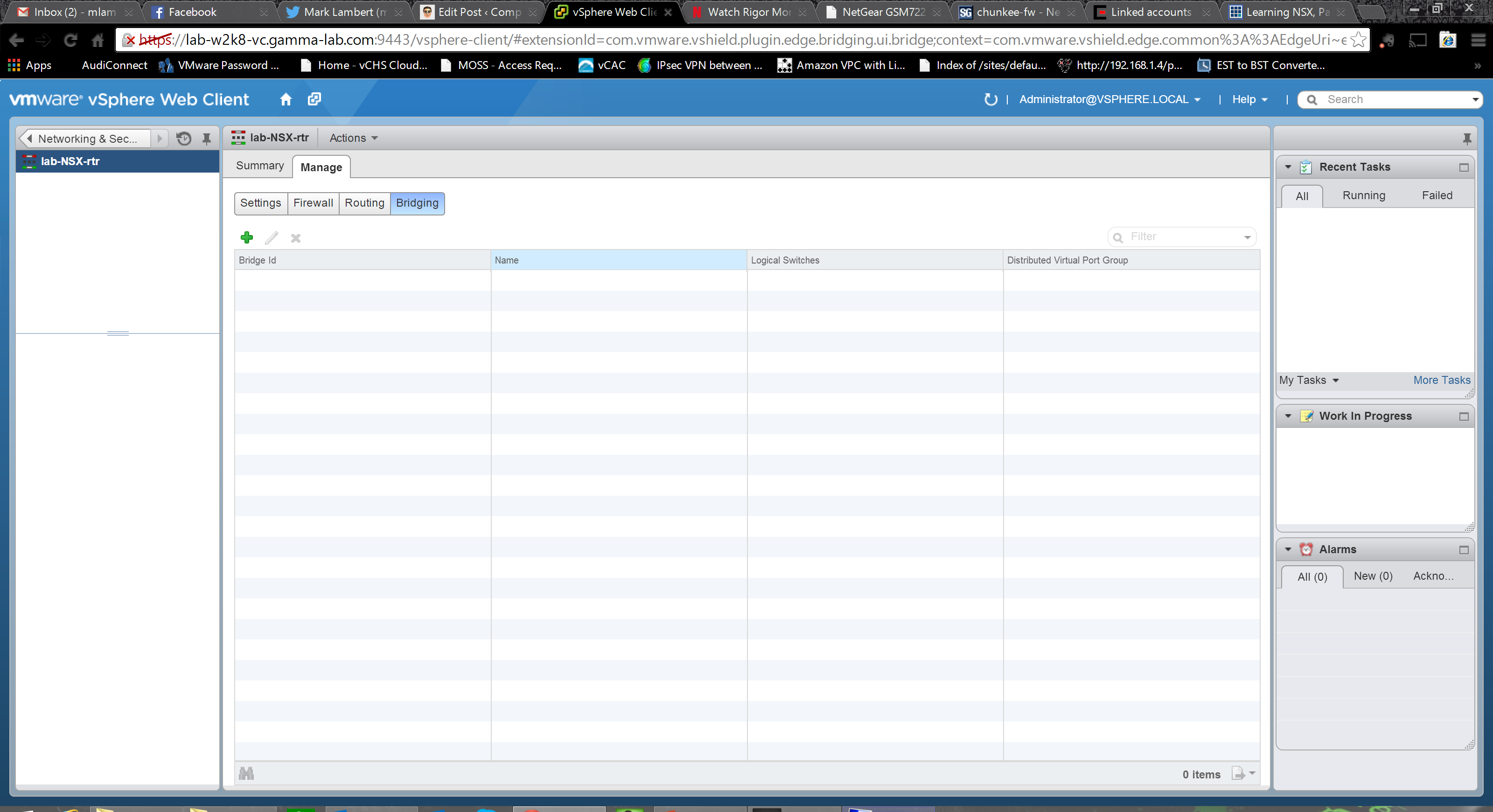
Very easy configuration: add a name for the new bridge group and the two port groups that are being bridged:
As you can see there are a huge number of virtual guest environment use cases that can be covered with the rich set of capabilities represented by both the NSX Edge and Logical router. Next entry we’ll spend some time considering possible architectures that would be difficult before NSX, but become simple once it has been deployed. Stay tuned!
