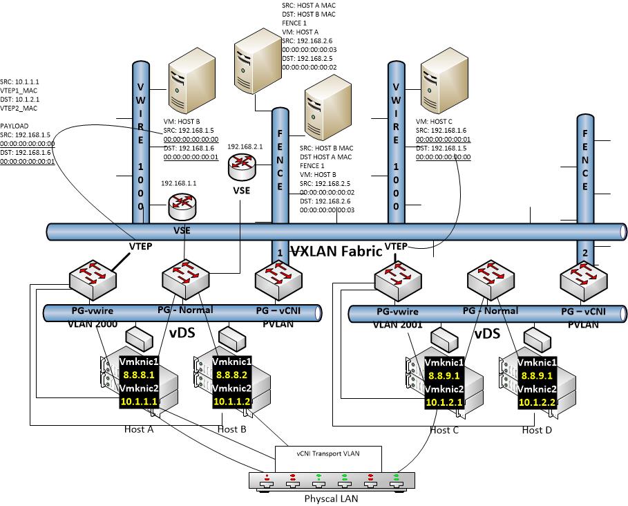
I decided to take a shot at diagramming something that is really difficult to capture in one picture and try to not have it dissolve into an utterly confusing mess: VXLAN and vCDNI coexisting in one provider foundation. I’m pretty sure I failed, but wanted to get it posted for posterity anyhow! The info is all there, but I think it ended up too busy to be meaningful:
There are a few core concepts here that are worth noting even if the picture is confusing. Ground rules to keep in mind when trying to digest complex virtualized network scenarios like this one:
- In vSphere all networking scenarios ultimately boil down to a port group in a virtual distributed switch in vCenter. This is a core networking construct for vSphere at this point and these new technologies overlay it, they do not replace it. Of course you can replace the vDS with equivalents like the Nexus 1000V or with something superior like Open vSwitch (Nicira now AKA VMware NSX and coming soon to a vCenter near you!), but for now we’ll still with the standard bits
- VXLAN is MAC in UDP, This means that the idea is to layer a virtual switch fabric, the VXLAN fabric, over an already virtual fabric (the vDS fabric). Each virtual uplink out of the VXLAN fabric is called a “VTEP” (virtual tunnel endpoint) and is associated with a dedicated vmkernel NIC which is in turn associated with a pNIC and has a real IP address. A VLAN can be associated as well to keep the traffic isolated, and this is the IP channel by which traffic will exit one VXLAN endpoint, travel magically across a layer 3 boundary, andenter a far away VXLAN endpoint. In the picture above this is represented by the traffic flow into and out of the “virtual wires”. Virtual wires are basically the port groups within the VXLAN and are the attach points for guest vNICs. In the picture above Hosts A and B share a physical layer 2 domain and IP subnet and Hosts C and D share a physical layer 2 domain and IP subnet, and they are connected by a physical layer 3 switch
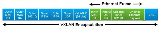
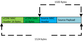
The VXLAN Frame Header - vCDNI is a MAC in MAC technology. What this means is that it cannot natively cross layer 3 boundaries. The idea for vCDNI is that you can stretch virtual subnets across hosts in a cluster. So for example in a cloud provider scenario, you might have a tenant whose VMs live on 3 different physical hosts, but who share a common network configuration. Of course this can also be done with port groups in a traditional vDS, but in this case all of the traffic must also be represented on the physical LAN. This means you are stuck with a 12 bit VLAN limit (4096) and you also cannot use conflicting IP space (at least not without implementing a fairly complex virtualized physical network architecture). The way vCNI circumvents these restrictions is by imposing its own overlay structure. It utilizes private VLAN port groups and a concept of “fence IDs” to define networks, rather than VLANs. vCNI prepared endpoints understand these identifiers and can move traffic accordingly. When Host A has a request from a given “Fence ID” homed VM to talk to another VM in the same Fence ID but located on Host B, the MAC in MAC comes into play. The entire ethernet frame of VM A is encapsulated with a new frame header destined for Host B and tagged with the VLAN being used for transport. The frame is then sent out the physical NIC to Host B who receives it, strips off the physical network ethernet header, and decides what to do with the vCDNI packet based on the vCDNI data (Fence info).

vCDNI Header - All of this might leave someone wondering how the heck traffic manages ingress and egress from these proprietary overlay networks (note: VXLAN is something of a standard and does have some physical network support from Cisco, but lets leave this aside for now as well). The answer from VMware is that all of these network overlay constructs rely on the vShield Edge Device (not known as vCloud Network and Security). The VSE devices are managed by the central vShield Manager, configured from the VSM portal, and can be setup to attach to both VXLAN and vCDNI segments and provide layer 3 routing out of them and into other overlay segments (in the case of vApp networks routing to vOrg networks on vCloud DIrector and the vCloud Hybrid Service), or to external networks (other port groups, the provider external port group on vCD, etc)