
Over the past two entries we have gone from being NSXless to having a full NSX foundation laid in a fairly painless set of steps. Next it is time to actually start to use the technology for something interesting. The true power of overlay network comes from two key areas: agility in the creation and management of layer 2 domains and the collapse of higher layer capabilities into the compute plane. We’ve seen the former in action with VXLAN and the way NSX leverages the VXLAN foundation to build managed dynamic L2 environments. The next piece is layer 3 and above. Being able to actually route, load balance, filter and intelligently direct traffic within the hypervisor enables enormously powerful consumption models. Past versions of VMware vShield Manager provided a simple “Edge” device which had load balancing, firewall, NAT, static routing, VPN (IPSEC and SSL) and DHCP capabilities. It was fairly similar to a virtualized version of a high-end home office firewall/router appliance. There were neat bells and whistles like high availability with very smart failover and the ability to have up to 10 interfaces for guest network usage. It also came in a host of sizes based on load and throughput requirements so it was resource efficient. So why change it? Well the good news is that NSX provides an additive experience. The traditional vShield type Edge is still available in NSX, but vastly improved. In addition, NSX provides the ability to deploy a proper virtualized router. A device which can actually participate in OSPF domains! That’s great stuff and is a capability of both the Edge appliance as well as the dedicated logical router appliance which is a subset of the Edge functionality plus bridging which we’ll explore in the next entry. For now let’s get started first by creating a Edge device.
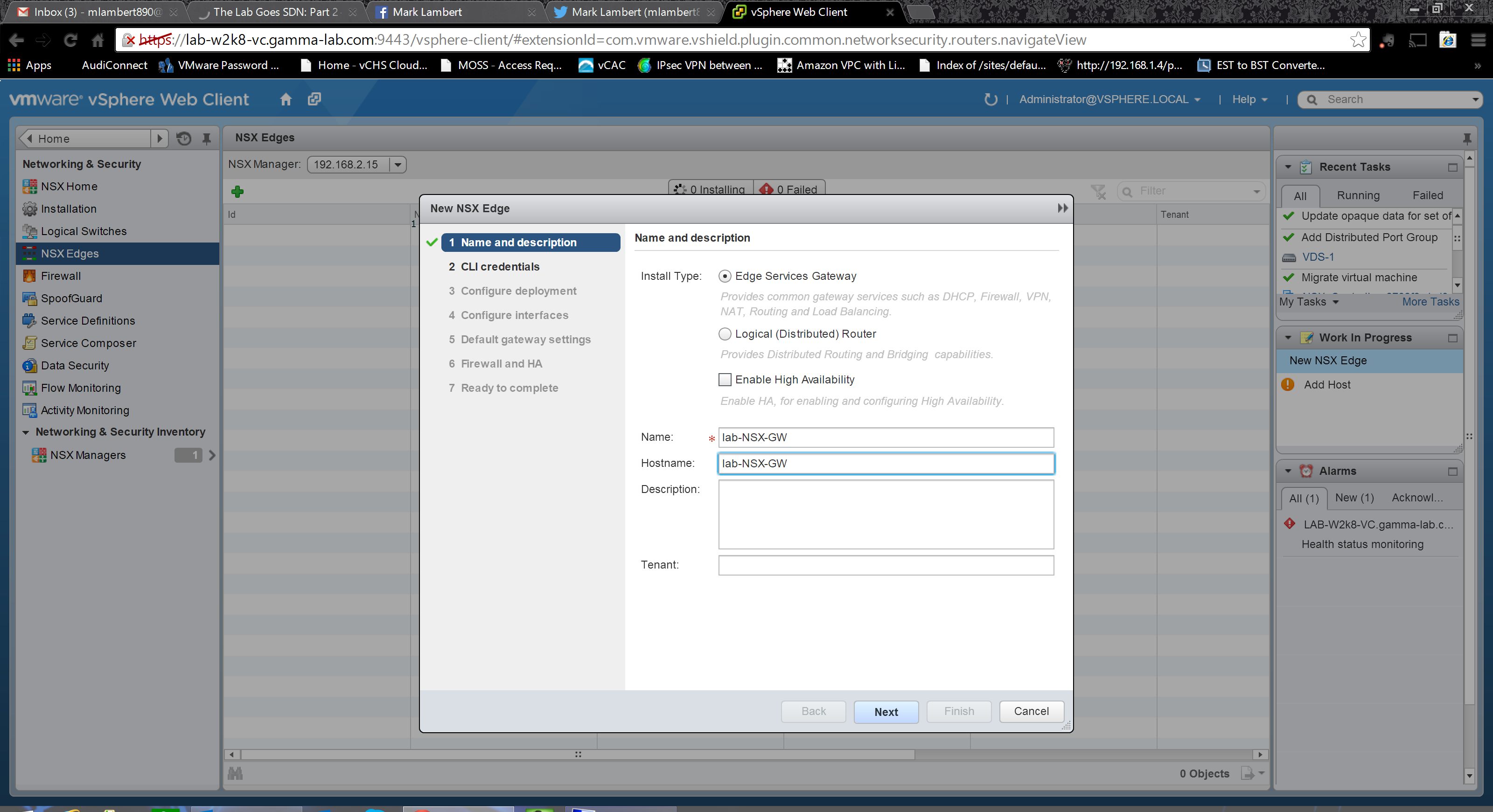
As with all NSX operations, we initiate from the Network & Security plugin. This time in the left hand menu pane we’re selecting “NSX Edges”. One interesting footnote; I actually lost my NSX plugin in the web client and nothing seemed able to bring it back. Skipping right to the resolution, the culprit actually turned out to be a stalled Windows update to .NET. Once I got Windows fully updated and WU healthy, vCenter magically got itself back into shape (following a final reboot). The moral of this story, to me at least, is that we really need a containerized version of vCenter running direct on hypervisor. Anyhow, enough of that. From NSX Edges, we’re going to click the green plus sign in order to add one. The New NSX Edge dialogue gives us a few interesting options right off the bat. First, we can see the traditional Edge Services Gateway (which we’re selecting this round). Below it, however, we can see this new construct the “logical router”, as discussed above. We will deploy one of those as well. Lastly we can see the option to deploy the Edge VM in an HA state. I’m leaving this deselected for the lab as resource usage is more important than availability. The last step is to provide both a descriptive name and hostname for the VM, then click Next:
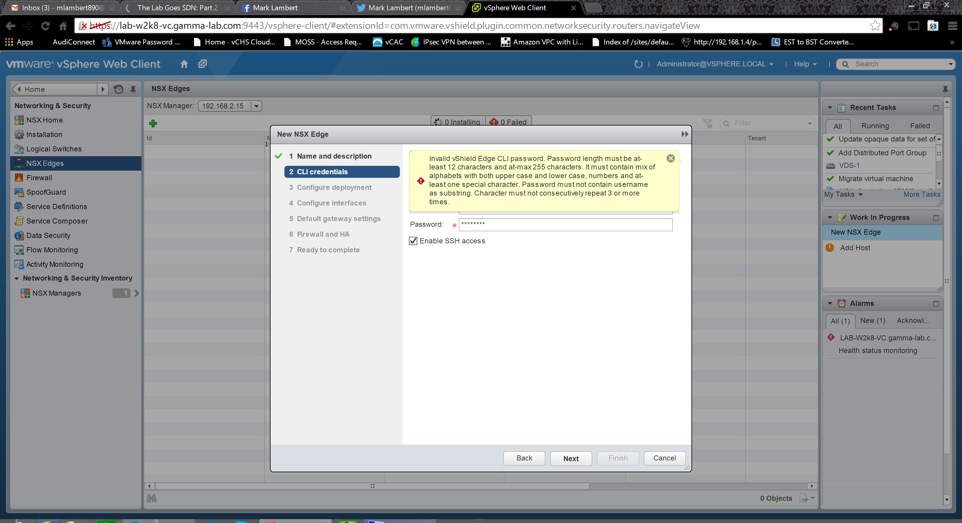
Next up is to set the appliance password. Note the password policy is very strong here. 12 characters, upper and lower case mixed, numeric and at least one special character. A pain for the lab, but a good practice for production anyhow:
With the password set we move on the the deployment options. Select a datacenter to deploy the VM into as well as a size. Size determines the number of vCPUs which will be allocated as well as the RAM. Obviously the larger the VM, the higher the volume of traffic it can process. Common use cases for the larger sizes would be a high number of IPSEC tunnels or an extremely complex firewall ruleset. There is also an option to turn off automatic generation of control plane traffic flow service rules. This is a case where this should only be selected if a specific design and implementation requires control beyond what automatic generation can provide. Last step is to add resourcing info for the Edge appliance VM:
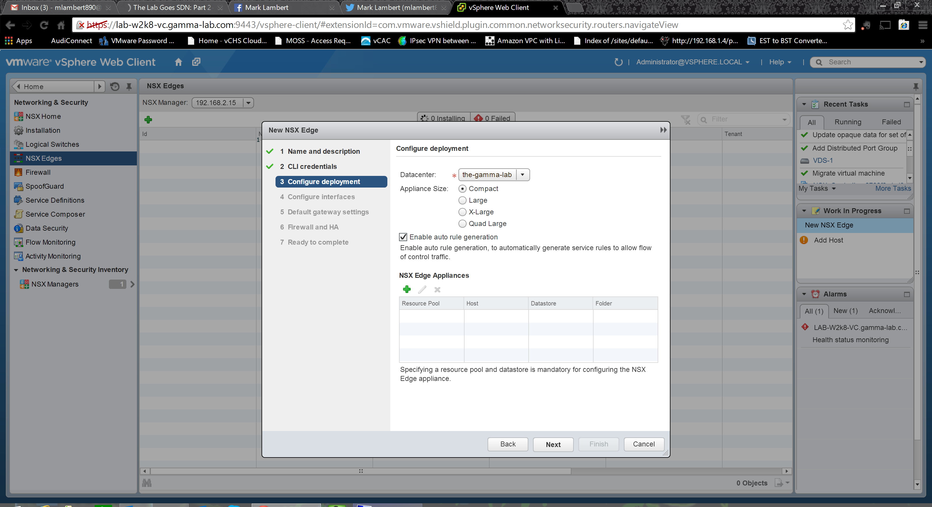
Select a cluster, datastore and (optionally) a host. Note, deploying to vSAN again just to show off!

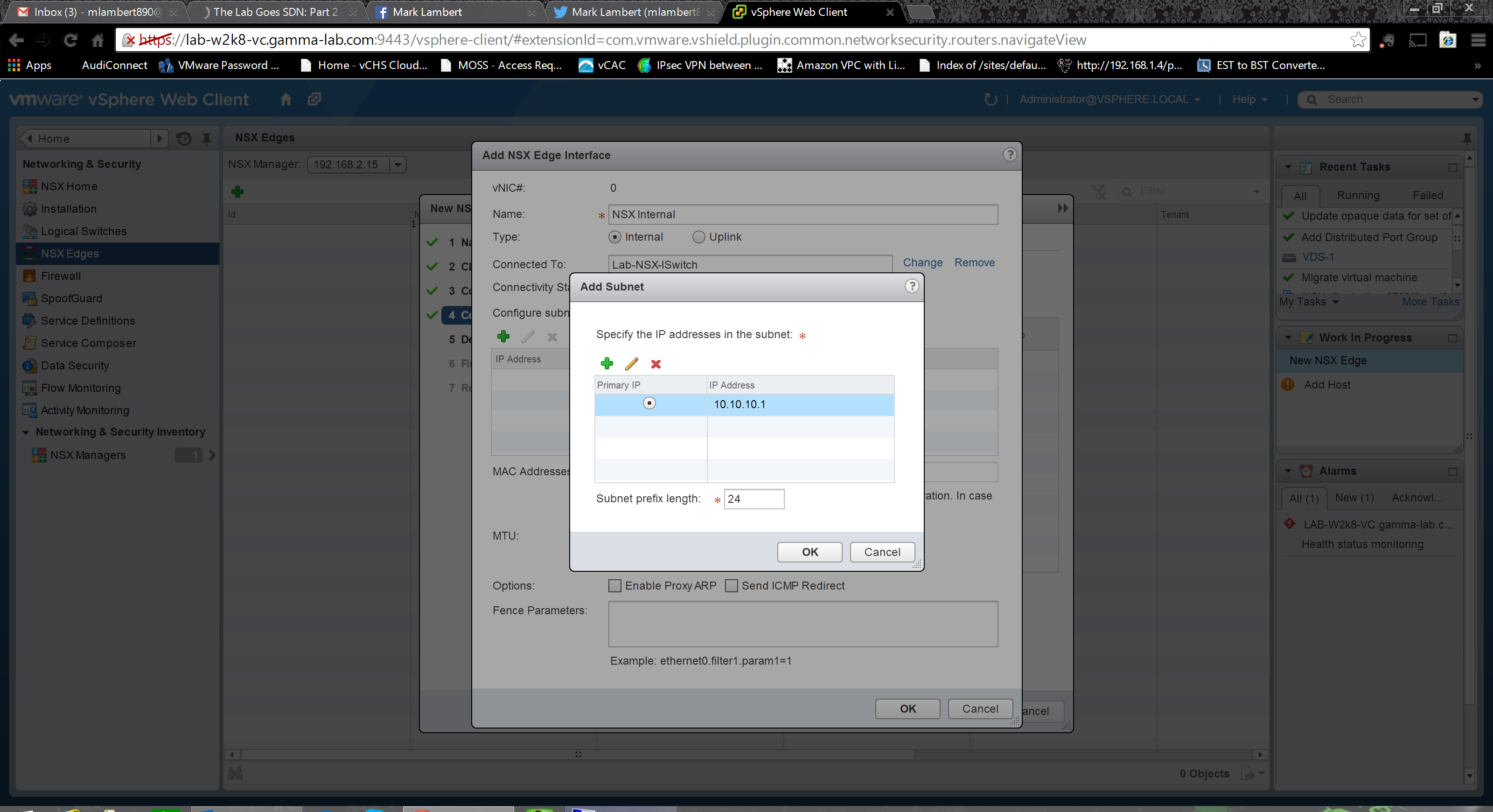
The next step is where the real magic begins. Here we are creating and configuring the network interfaces of the Edge appliance. If you think about what we’re doing here from the perspective of legacy network engineering, it really is amazing. Through an easy wizard driven GUI, we’re literally creating and addressing network uplinks. Extremely cool. Each interface is classified as either “Internal” or an uplink “external” and should have corresponding connectivity which matches. I point internal interfaces towards the NSX logical vswitch (VXLAN vwire environment) that the guest VMs will attach to, and external interfaces at a port group that has a physical route path out of the lab network. In this respect the new edge is very much like the vShield Edge in a vCloud Director scenario, where internal interfaces would be connecting to a tenants organizational network while external interfaces would be connecting to the provider external network. After selecting the type of interface, provide it a name and then set its vswitch connectivity. The last step is to provide an IP address for the new interface. Of course this IP should be valid for the vswitch and port group the interface is being connected to:
With all options complete, we can now add another interface. There should be at least one internal and one external if the guest VMs will need to reach outside of the overlay network:

With both interfaces created and configured, we can move forward to the next step:

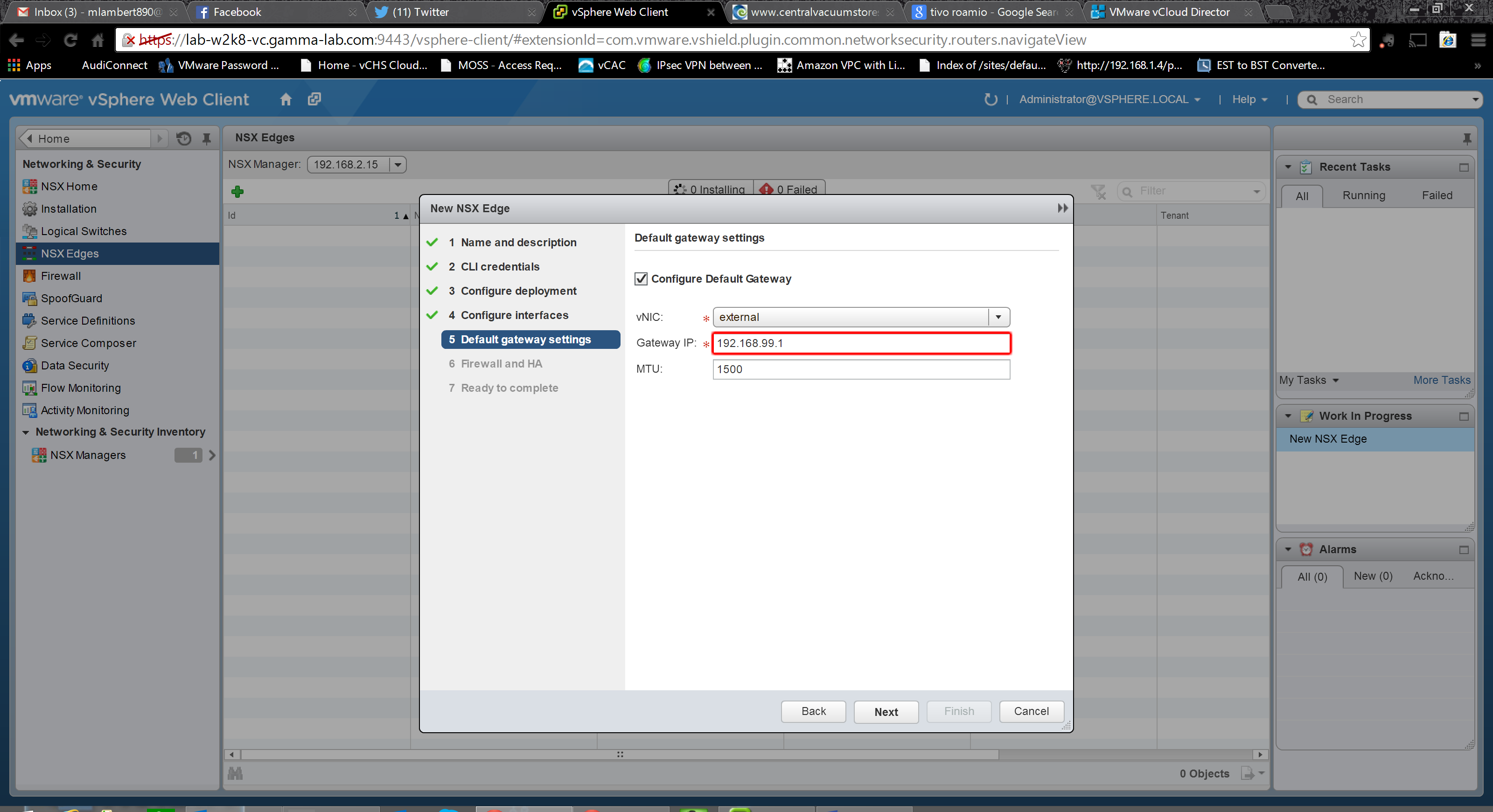
Since this is a gateway device, we should provide it with a default gateway (although this is optional). Select the appropriate interface and provide the IP of the next hop router on that subnet:

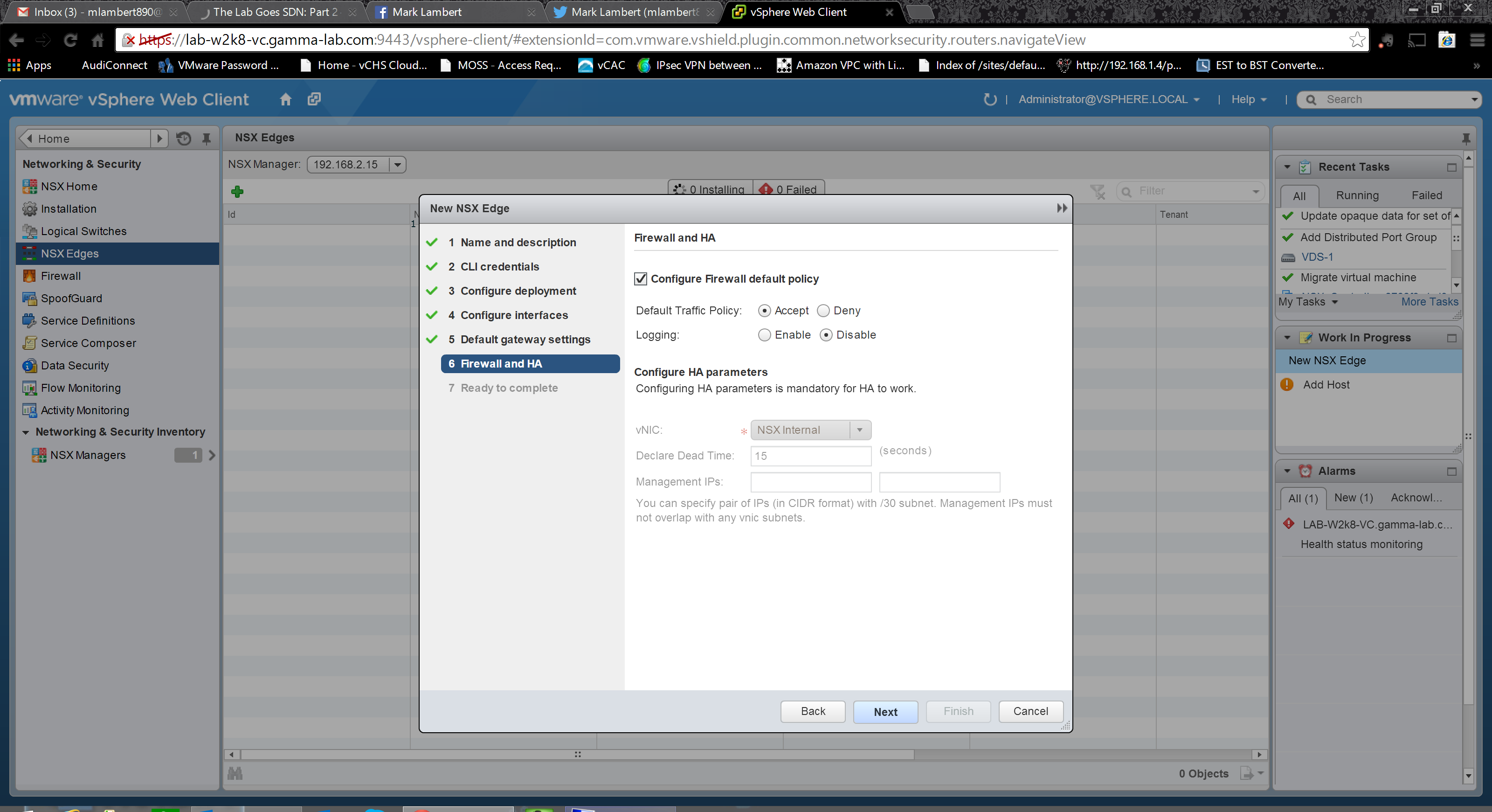
The last step is an opportunity to create a default firewall policy. Very useful for setting baseline security so the new appliance comes up configured. HA parameters can also be set in this dialogue box if the HA option was selected up top:
With all steps completed it is time to review and submit!
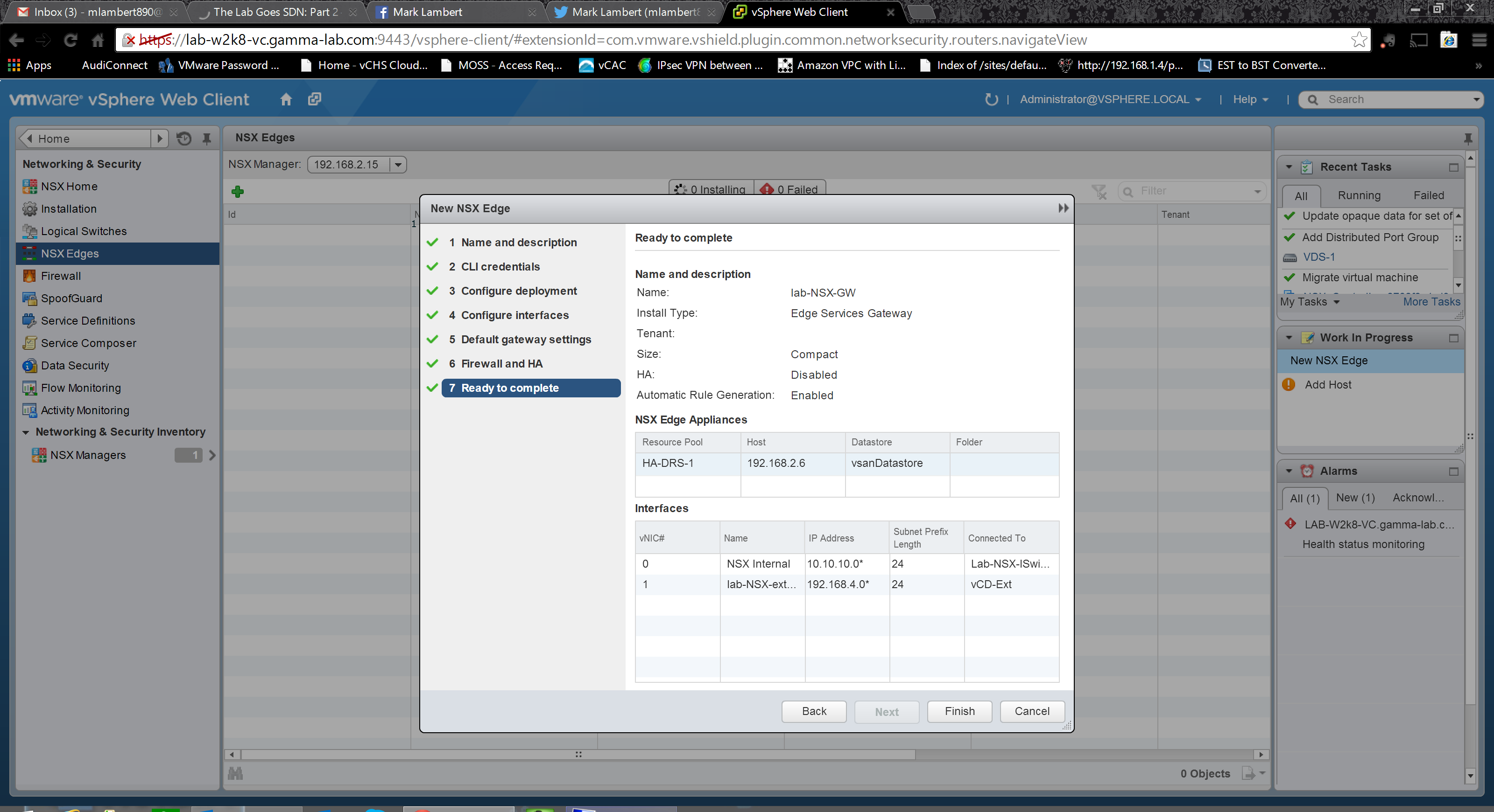 If everything is correctly configured, and there is sufficient host resourcing available to support he creation of the configured Edge appliance VM size, the appliance will deploy and come online:

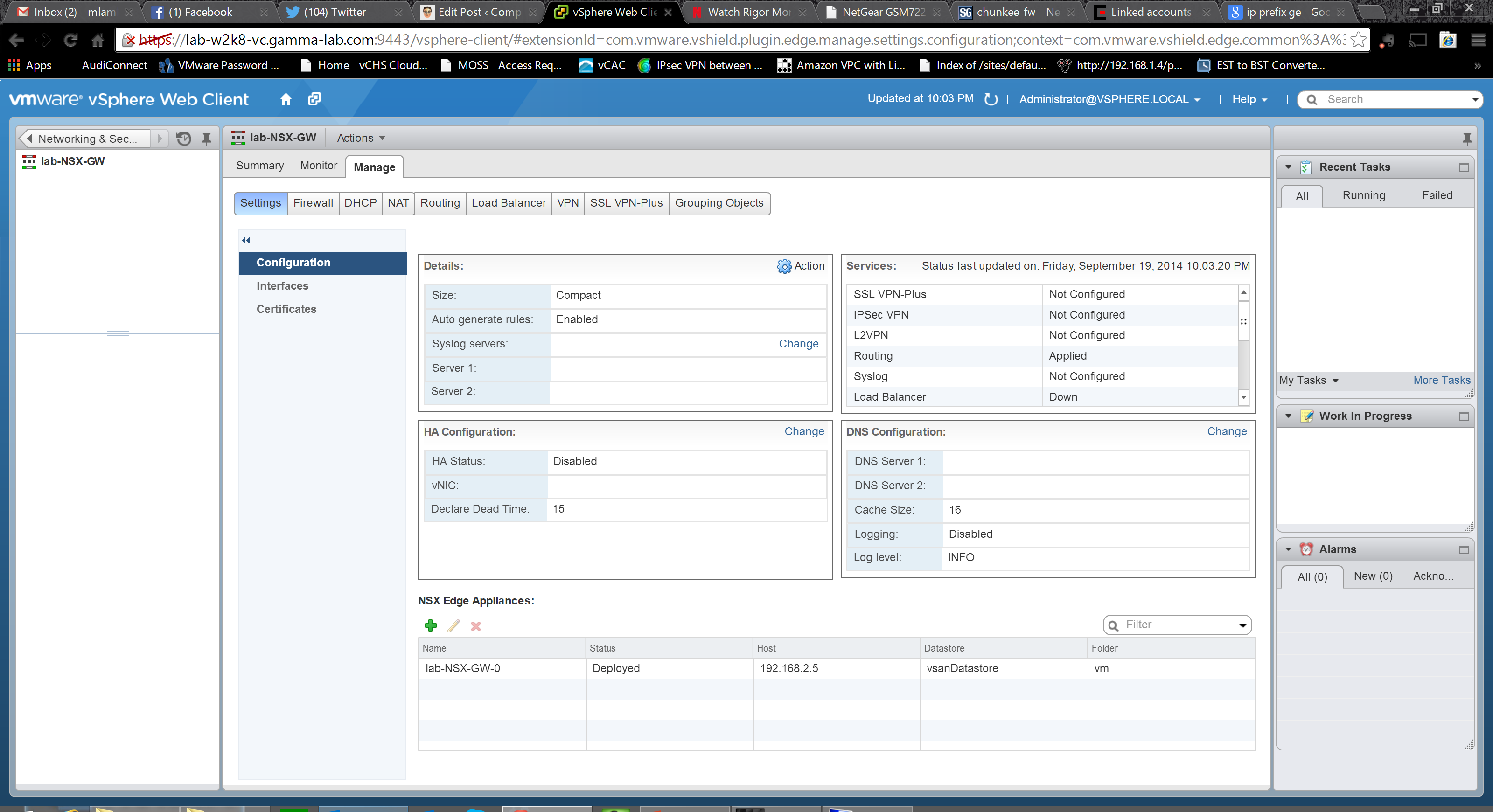
We’ve got a working Edge, so let’s see what it can do! For anyone familiar with the vShield Edge, this will be semi-familiar territory, but there is also a ton of new capability. Doubleclick on the newly created Edge device object to bring up the configuration page. The first stop is to head over to the manage tab. Look at all of those groupings! There are separate config hierarchies for Firewall, DHCP, NAT, Routing, LBS, VPN, SSL VPN and grouping which makes things very intuitive. Let’s start with the top level Settings group. First up is the Configuration page. Here we can modify the syslog configuration and logging options for the appliance. We can also check on what services have been enabled at a glance. There are also sections to modify both the HA configuration and the DNS settings. Finally, we can deploy a new appliance from this panel as well:
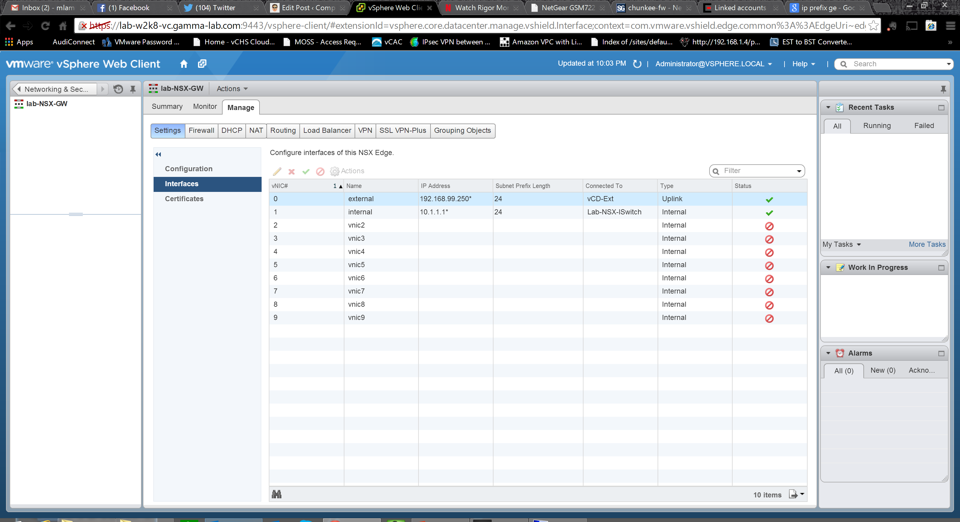
Moving one level down we arrive at the configuration page for the interfaces. Here we can see the aforementioned 10 available interface slots, two of which we configured during the deployment steps. We can modify or delete those, as well as add new ones:
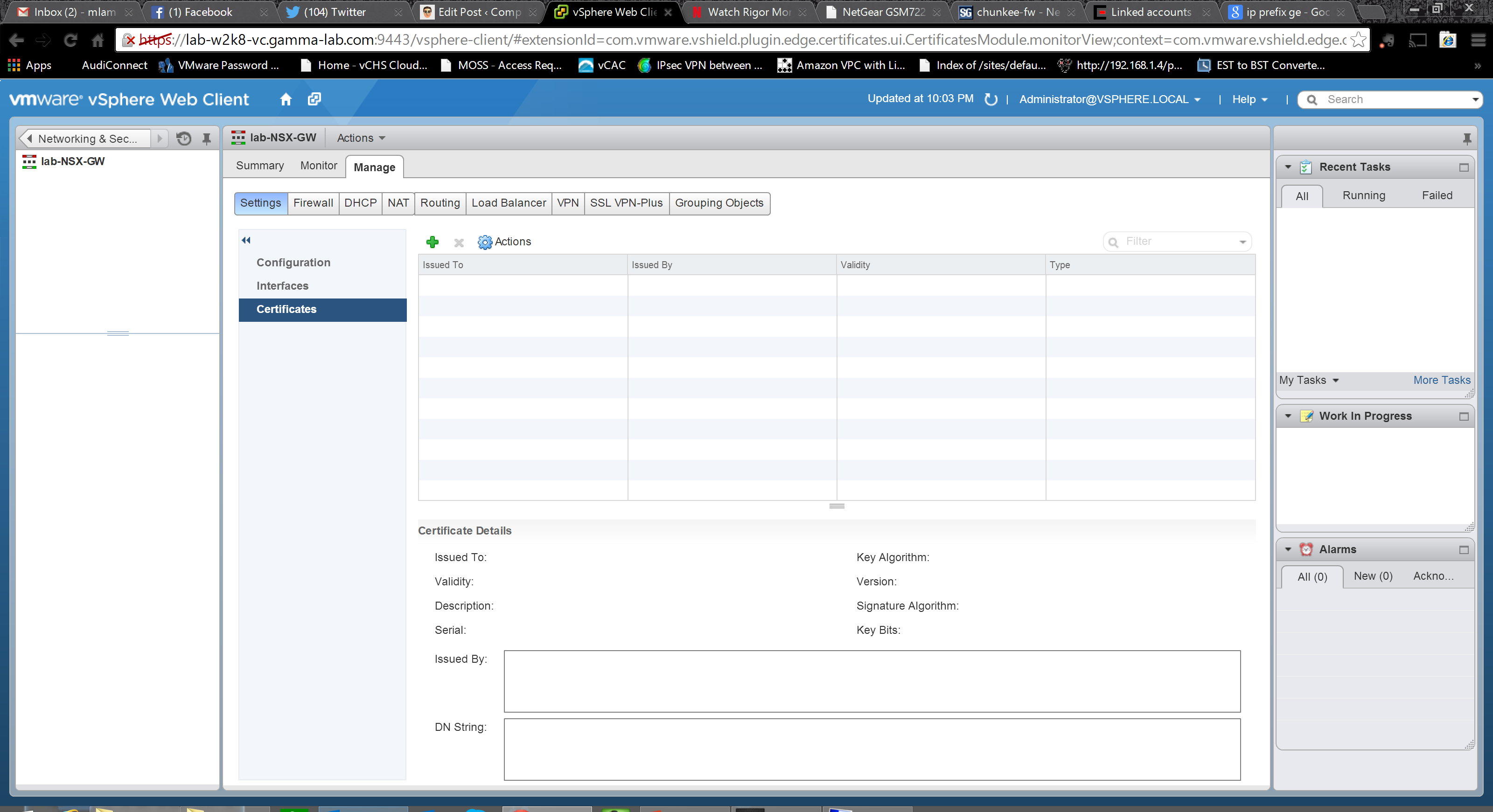
The final configuration area under Settings is for certificate management. This appliance reaches up to layer 7 and also supports VPN, so it is likely that it will need to be configured with one or more public certs. This panel makes complex cert management very easy:
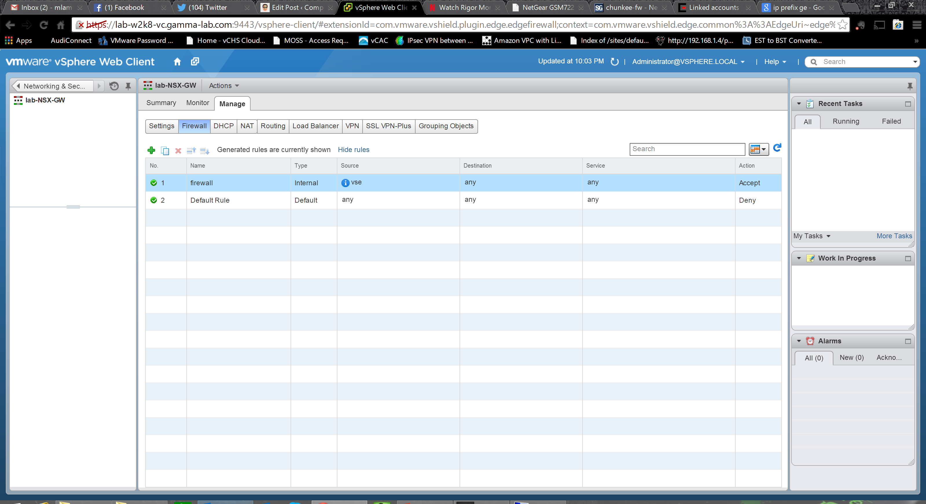
The next top level configuration grouping is for the Firewall. Very clean presentation with all rules listed in tabular format. Click the green “+” to create a new rule (providing the expected source, destination, service and action values) or delete or modify existing ones. They are processed in order and can be moved. Keep in mind that the bottom rule will “catch all”, but only the first rule that matches a traffic pattern will be applied (in other words a higher level “permit” will take precedence over a lower level “deny”, but would be rendered superfluous by a higher level deny), so plan rule strategy accordingly:
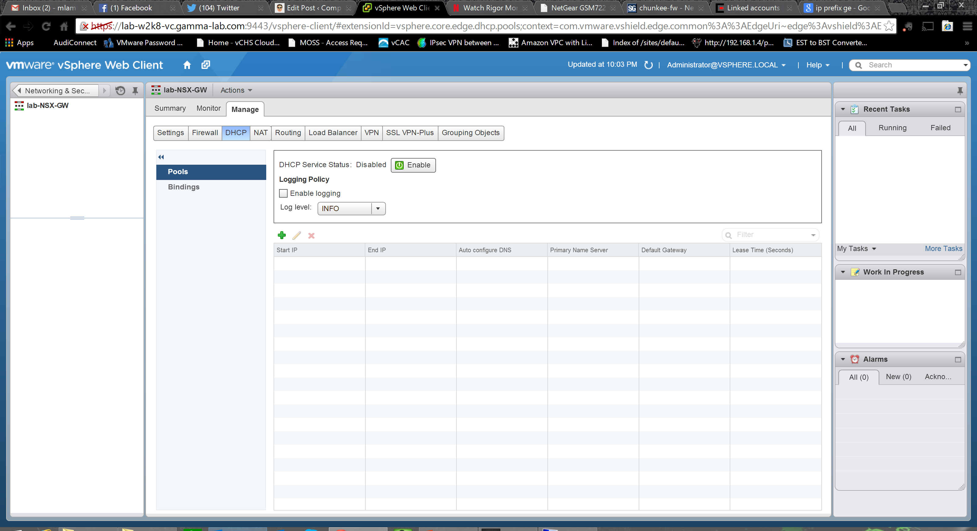
The next settings group is for the DHCP server. I can’t stress enough the utility of this option. When you consider software defined datacenter strategy, and the automated deployment and configuration of customer environments, having a way to bring guest OS instances onto the network before the first one is deployed is extremely powerful. Being able to manage (and orchestrate) that capability right in the network edge device is an even bigger bonus. The first stop is the Pools config block and the options here are very straightforward for anyone familiar with DHCP. You can enable the service, configure logging and create scopes (IP ranges that the DHCP server will service):
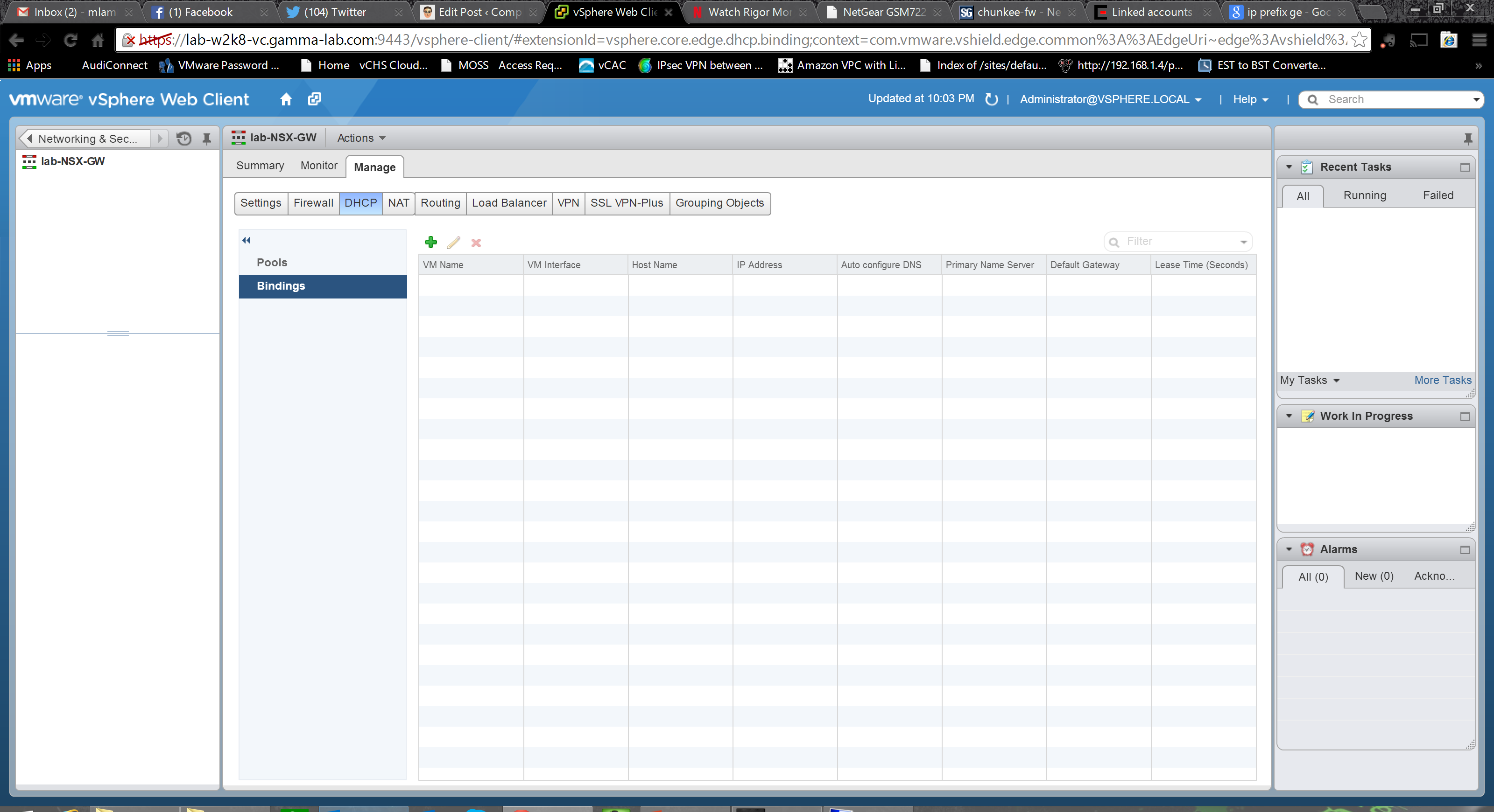
With the pools defined we can view and configure the Bindings. Bindings in this context are static assignments. What this means is that the DHCP server can actually be prepopulated with IP associations by VM ensuring that a specific guest instance will get a specific IP:
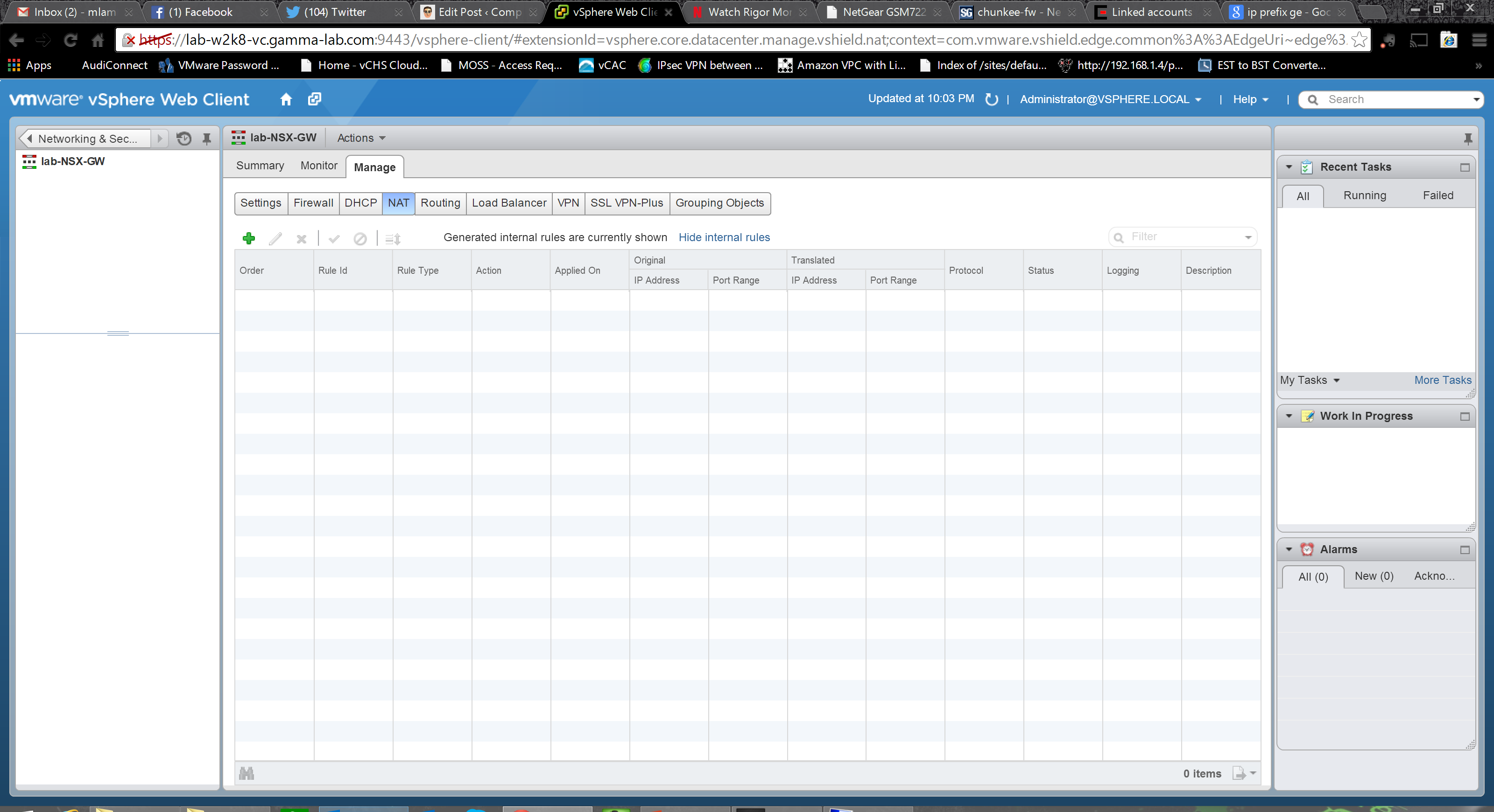
Next up is the NAT configuration. As an edge device, this section is critical. The rules come in two flavors, SNAT and DNAT. SNAT are source NAT rules which are for egress. The translate private internal IP address to the outbound gateway uplink address. DNAT are destination NAT rules which are for ingress. They are applied to one of the external gateway IP addresses and translate a specific inbound port to an internal address (changing the port as well if needed). And of course it goes without saying that in order to NAT traffic and have it flow, you also need corresponding firewall rules that permit it. The top level UI is very minimalist, click the green “+” to create a rule as usual.
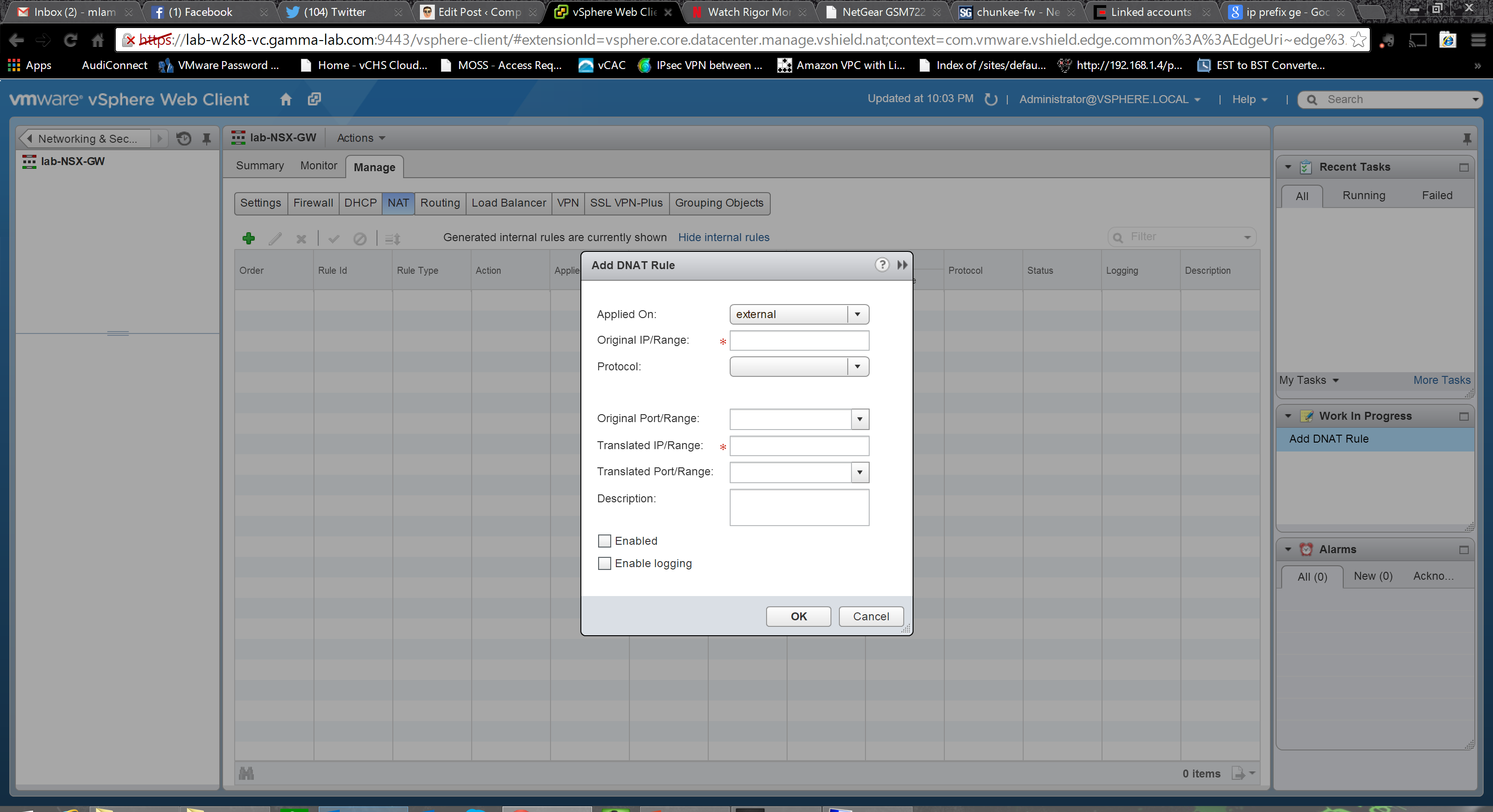
Here we see the options for a DNAT. We have the original IP range and protocol (TCP or UDP), as well as the original port range. Corresponding configuration must also be provided for the translation side of the equation – both IP and port range:
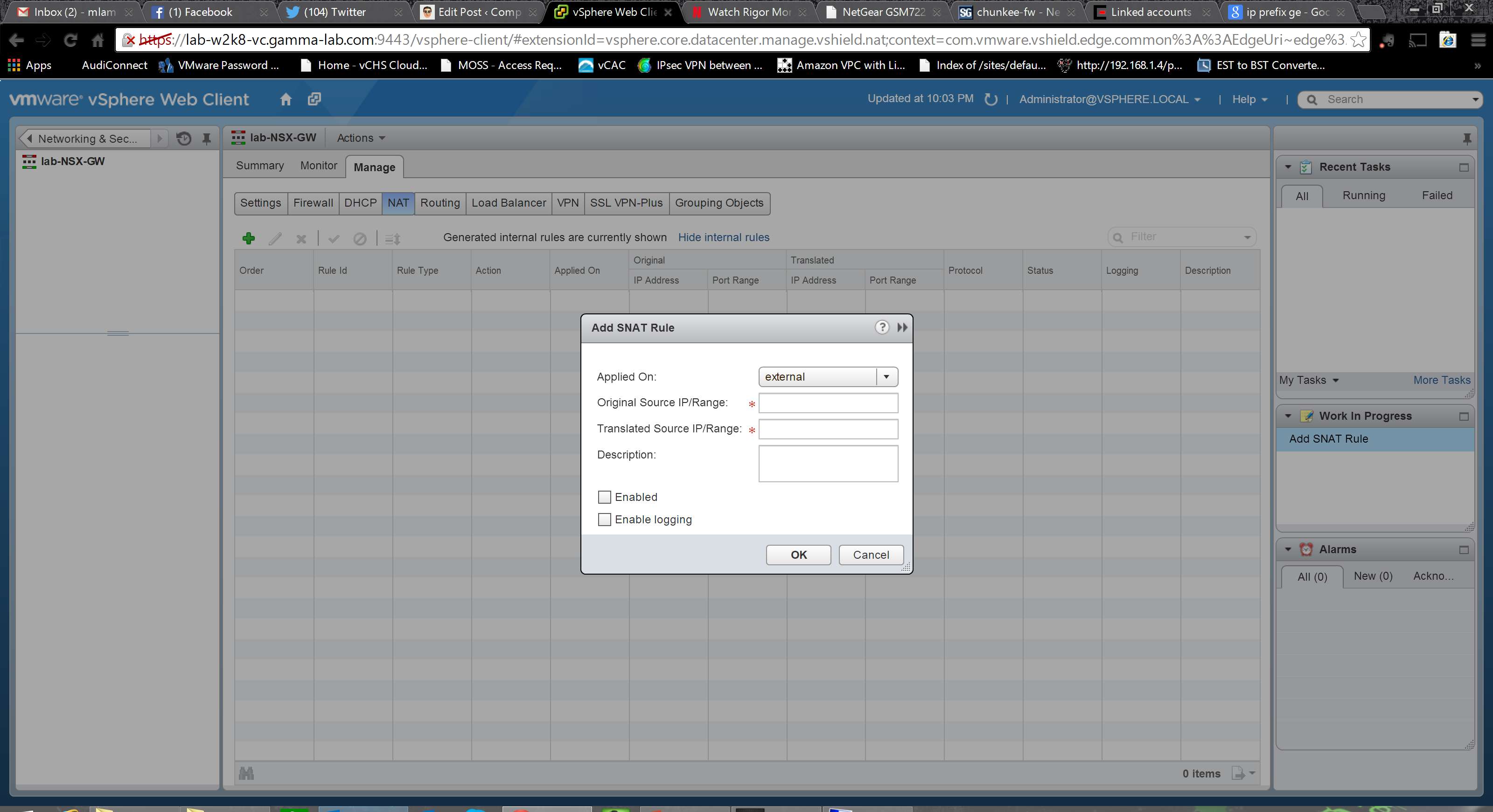
SNAT is simpler. Set the interface the rule is being applied to and provide both an original IP range and a translated IP range to start NAT’ing internet traffic out:
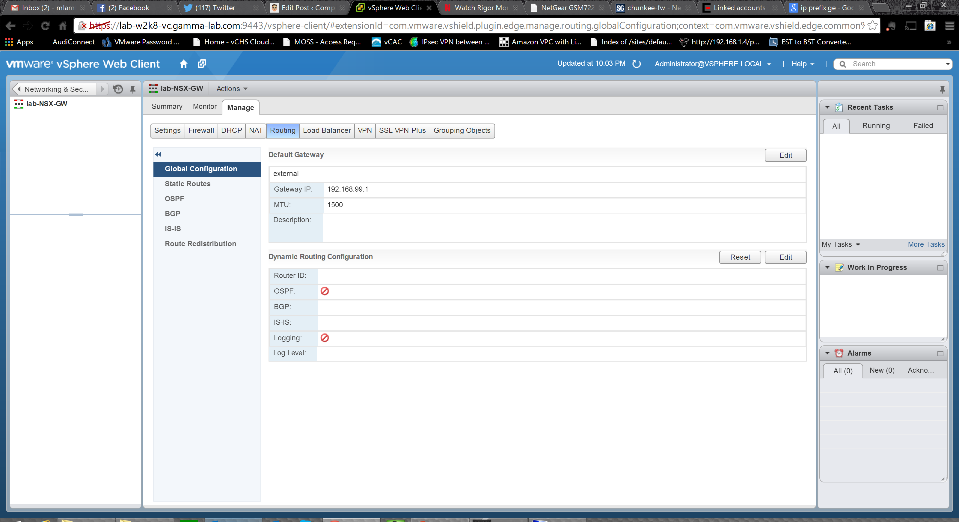
The Routing section is where things get really interesting and the true power of the new NSX flavored Edge is unlocked. It starts off with top level configuration. Set a default gateway for the router itself, if appropriate, and then enable the dynamic routing options. OSPF and even BGP(!) are supported. This is fantastic as, with these two protocols, 80% of both internal and external integration cases are covered. We can also configure logging in this section:
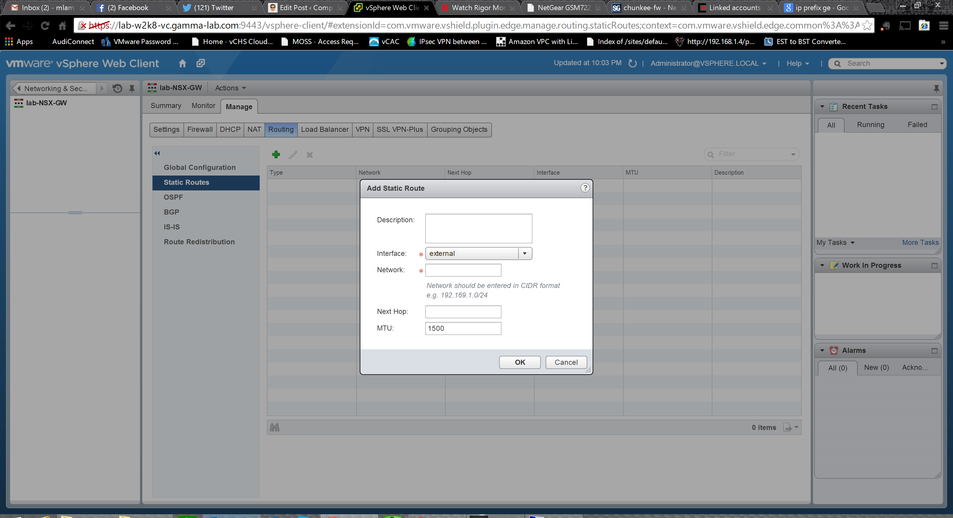
In the event that the logical router is being deployed into an environment without dynamic routing, static routes can still be created. Once again intuitive, Interface, network, next hop, MTU (powerful – per route MTU, this is fantastic), and of course a description field:
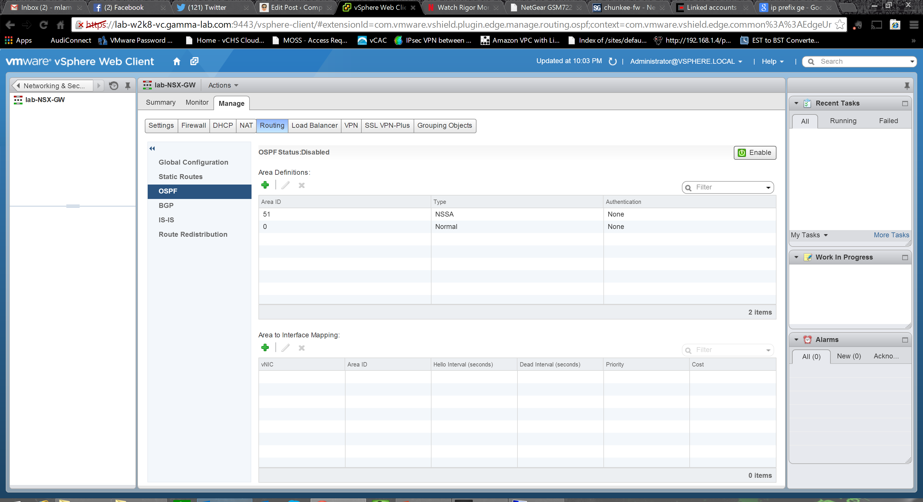
The OSPF tab is a bit overwhelming for anyone not familiar with the protocol, but will look like home to anyone who is. The fundamentals needed to get the logical router working in an OSPF area are here: protocol and forwarding addresses, definition of the OSPF area, and mapping of the area to an interface:
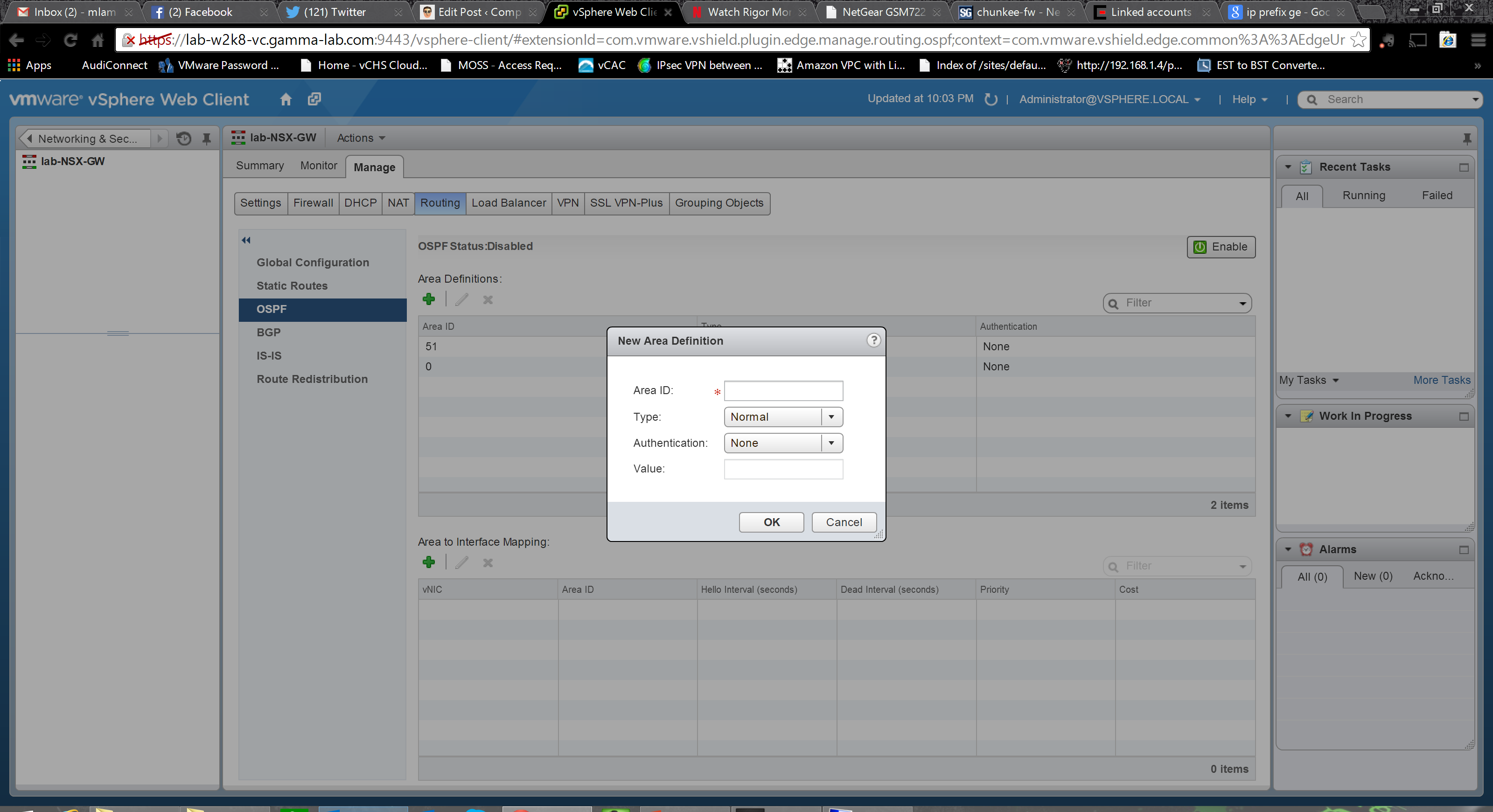
Adding an area we enter an ID, select a type (normal or NSSA – RFC 1587 “not so stubby area” for redistributing external BGP routes into OSPF) and an authentication method (MD5, password or none) as well as the authentication value (password or MD5 hash):
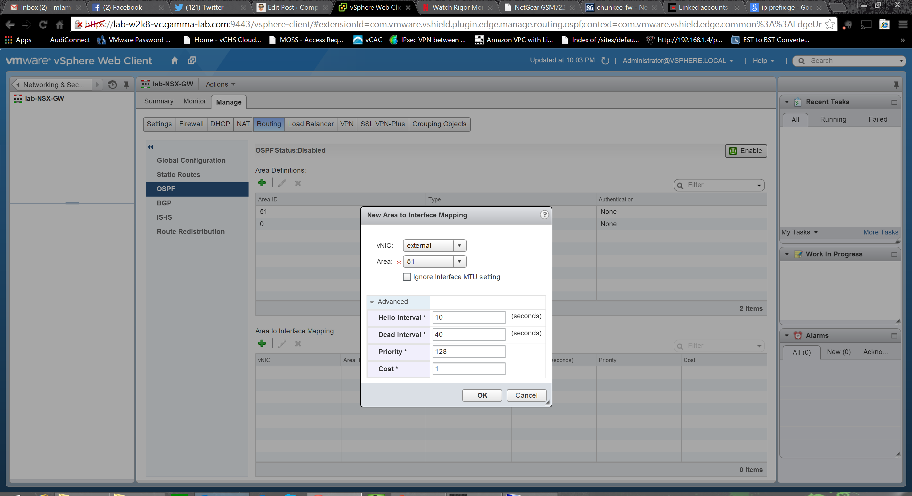
Once the Area is setup, we map it to an interface. Option here to ignore the interface MTU as well as advanced options to control protocol intervals, and set both priority and cost:
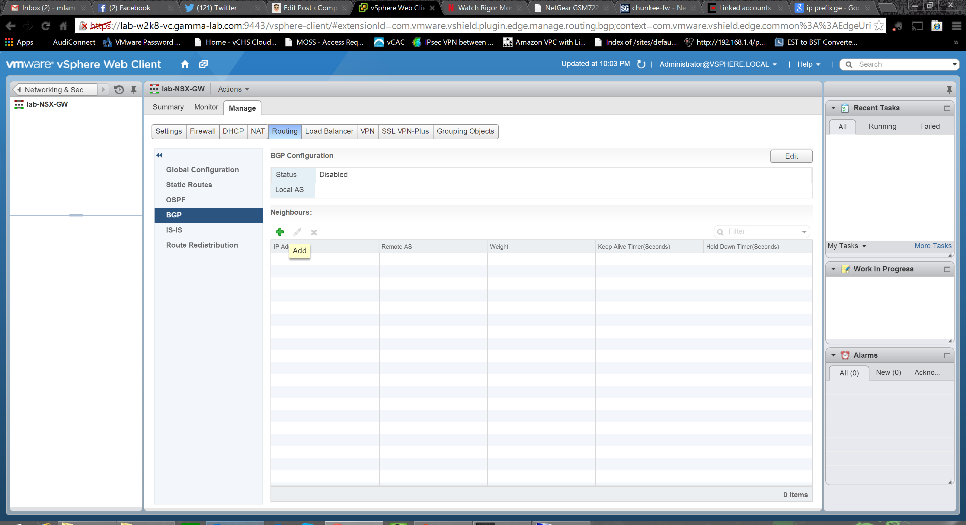
OSPF has our internal needs covered, so let’s move on to BGP to cover our external inter-org routing requirements. Once again, if you know BGP this is familiar territory. Up top we enable the protocol and assign our AS (Autonomous System Number – the identifier by which BGP peers identify each other and associate IP ranges with an endpoint). We also add our Neighbors – BGP peers with whom we are establishing a BGP routing relationship:
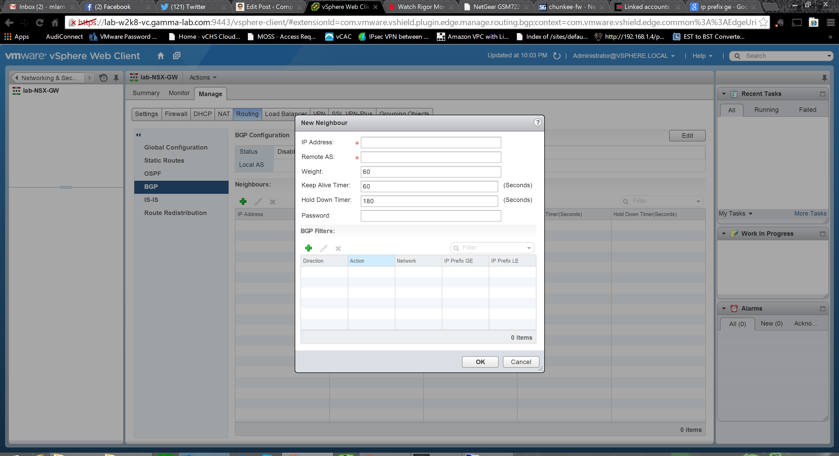
Peer configuration requires knowing a bit about your neighbor obviously. The remote organizations AS number is of course the starting point along with assigned IP address, as well as protocol and forwarding IP addresses. We can also enter timings and weightings and assign mutual authentication password. Once the foundation has been laid, we can also optionally add BGP filters:
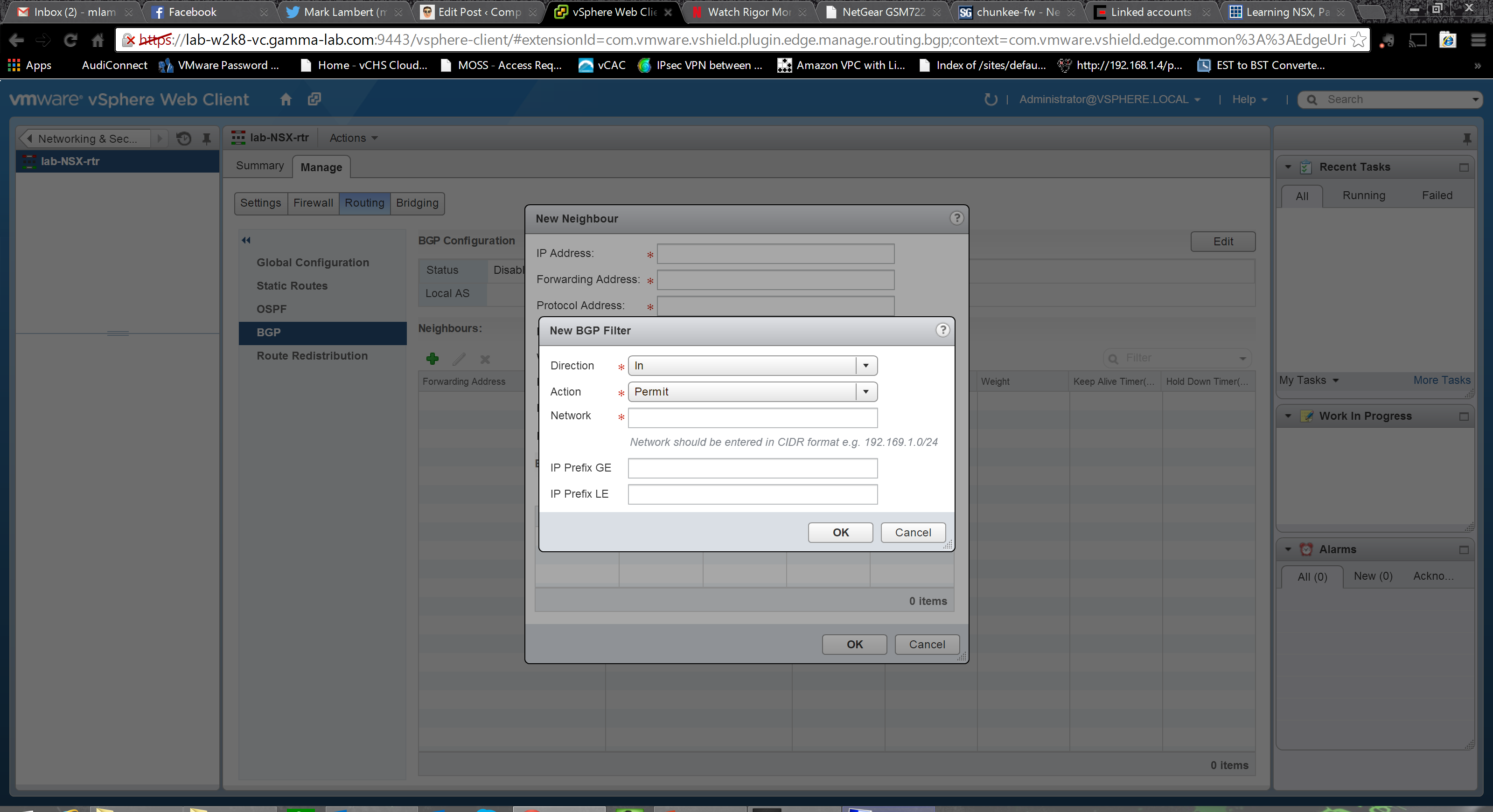
Adding a filter we set a direction (ingress or egress) and an action (permit/deny) on a specific network expressed in CIDR block format. We can also use IP prefix conditionals (GE – greater than or equal to, LE – less than or equal to) to apply to a range:
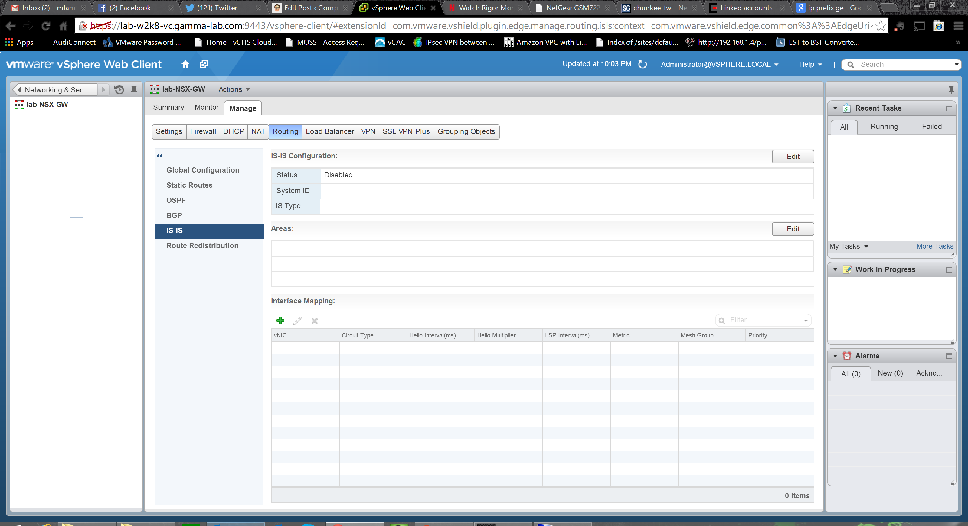
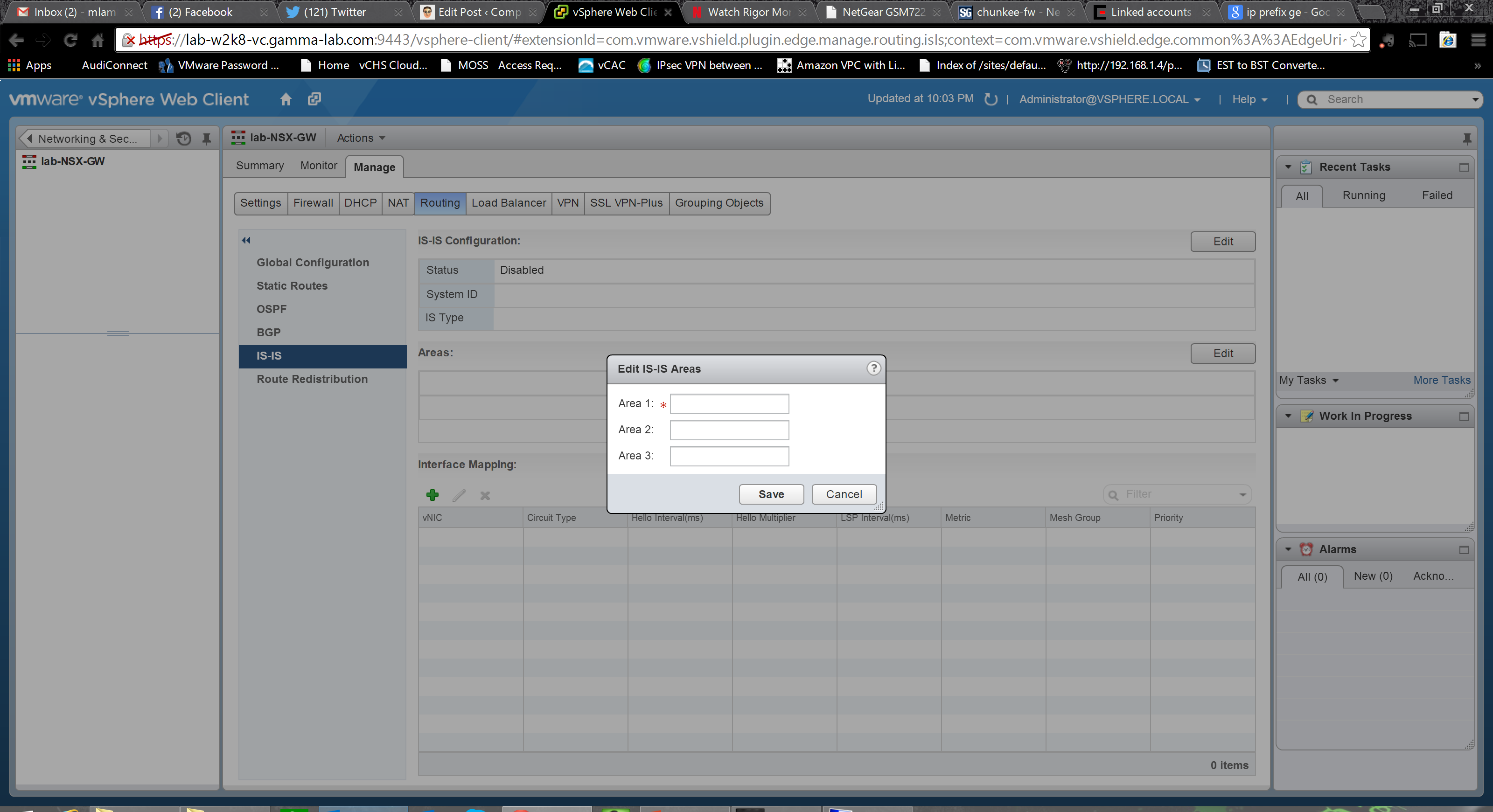
IS-IS is an internal, link state based, routing protocol. An alternative to OSPF, the key difference is that while OSPF was built as a pure layer 3 control plane protocol, IS-IS starts with a layer 2 view of its Intermediate Systems. As such it is a core component of the various IEEE advanced bridging protocols: 802.1ad, q and h. This is an extremely powerful option to have here. If you consider integrating with carrier stretched layer 2 topologies (like VPLS), ability to support the 802.1a family protocols (Shortest Path Bridging, Provider Bridging and Provider Backbone Bridging) can spell the difference between being able to actually participate in the extended L2 domain vs having the virtual network environment relegated to its own L3 domain (and consequently new IP space). It is also a solution for eliminating the need for yet another level of overlay abstraction, the SSL VPN or IPSEC TAP VPN which, while still available as options, create additional overheard. The base UI for configuring IS-IS allows us to configure a system id and Intermediate System type, create Areas, and map them to an interface:
Creating IS-IS Areas is easy:
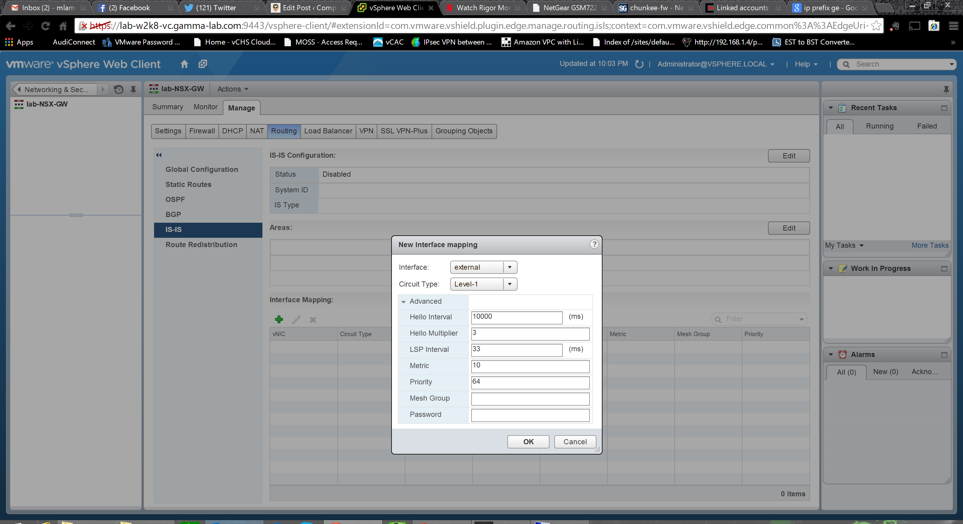
Interface binding follows the same convention as BGP:
We’ve got internal routing with OSPF. We’ve got external routing with BGP. Let’s link em! The Route Redistribution tab let’s us do just that:
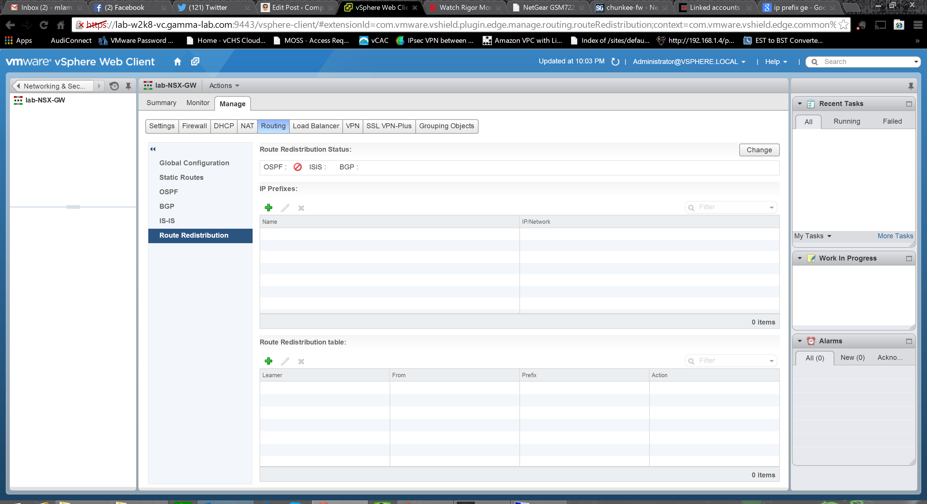
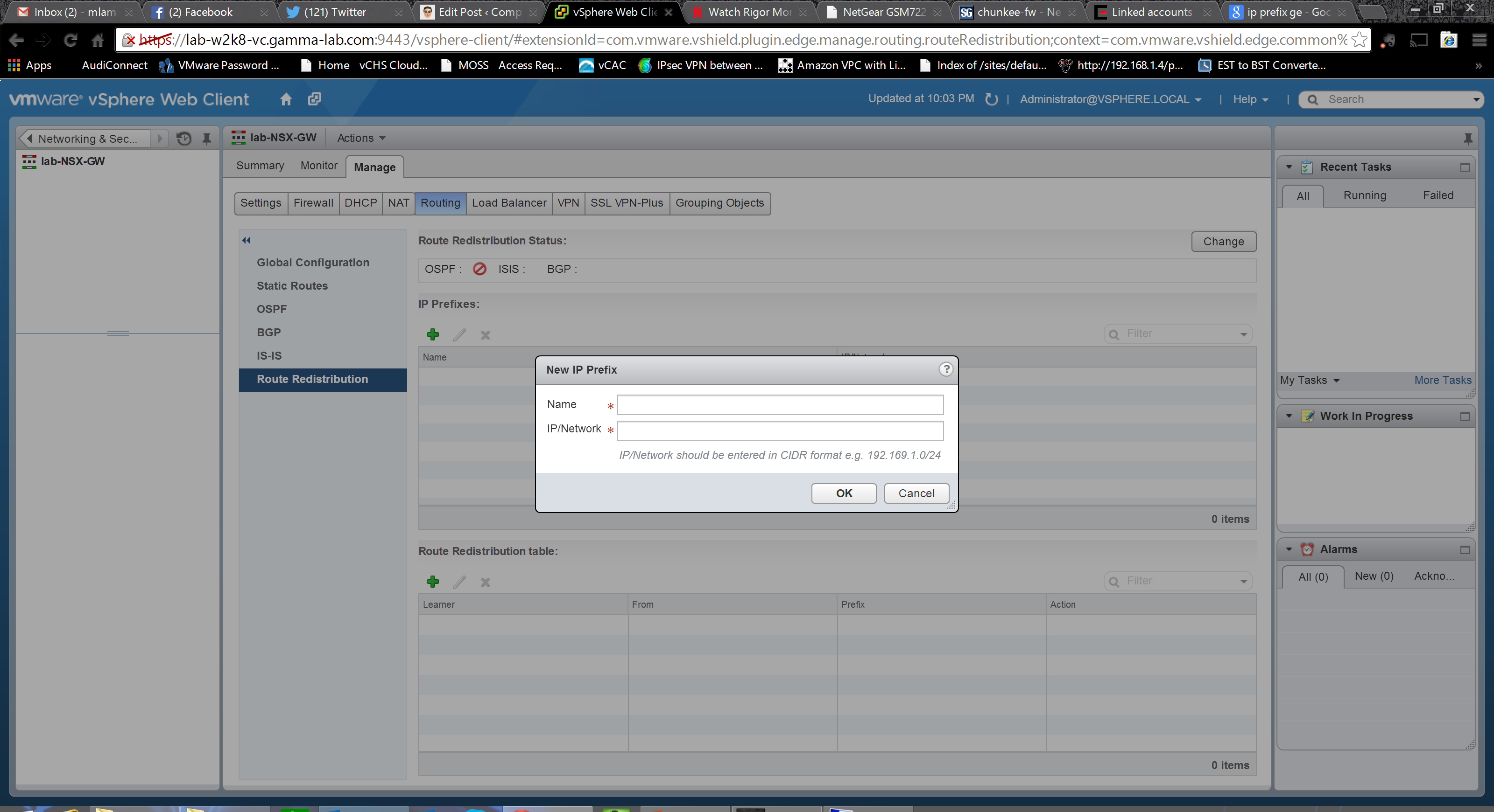
First we establish the IP prefixes for route redistribution. Name and CIDR notion network definition:
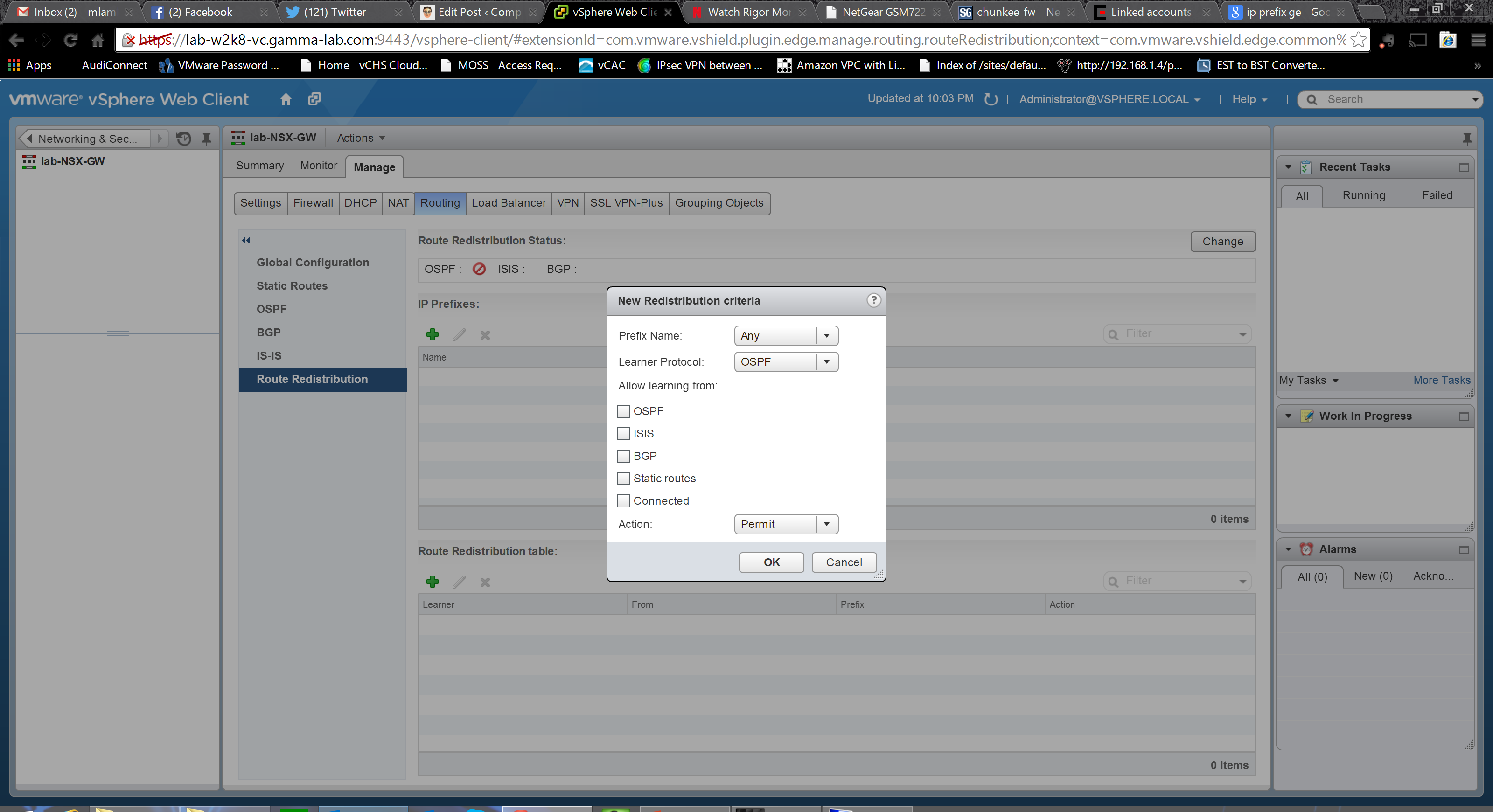
Next we create the redistribution criteria. Select the prefix (network defined above) and then set direction. The “learner” protocol is where the route is being distributed, the “learning from” entry is where the route is originating. Origination can be OSPF, BGP, static or directly connected networks. Destination can be OSPF or BGP:
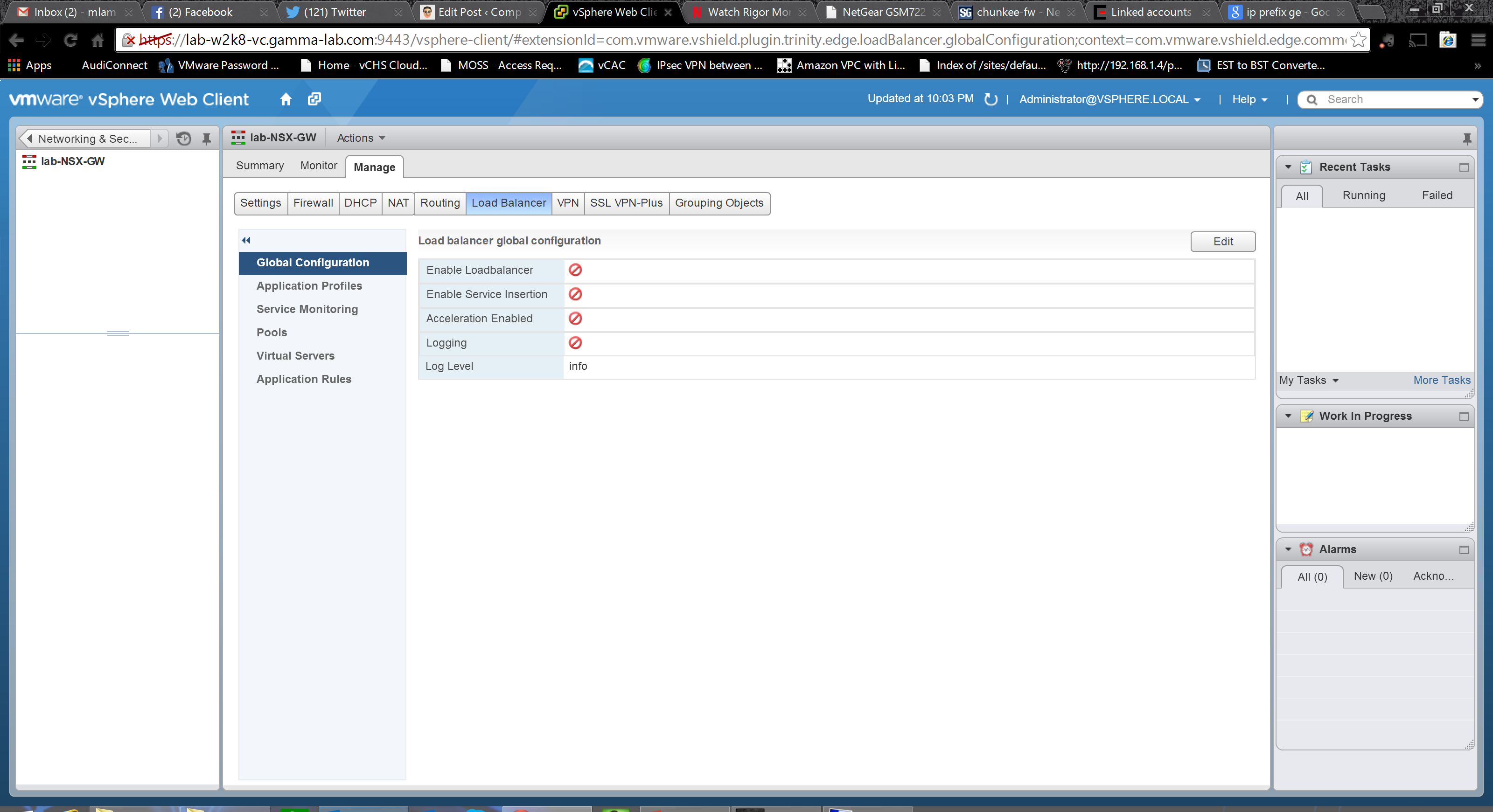
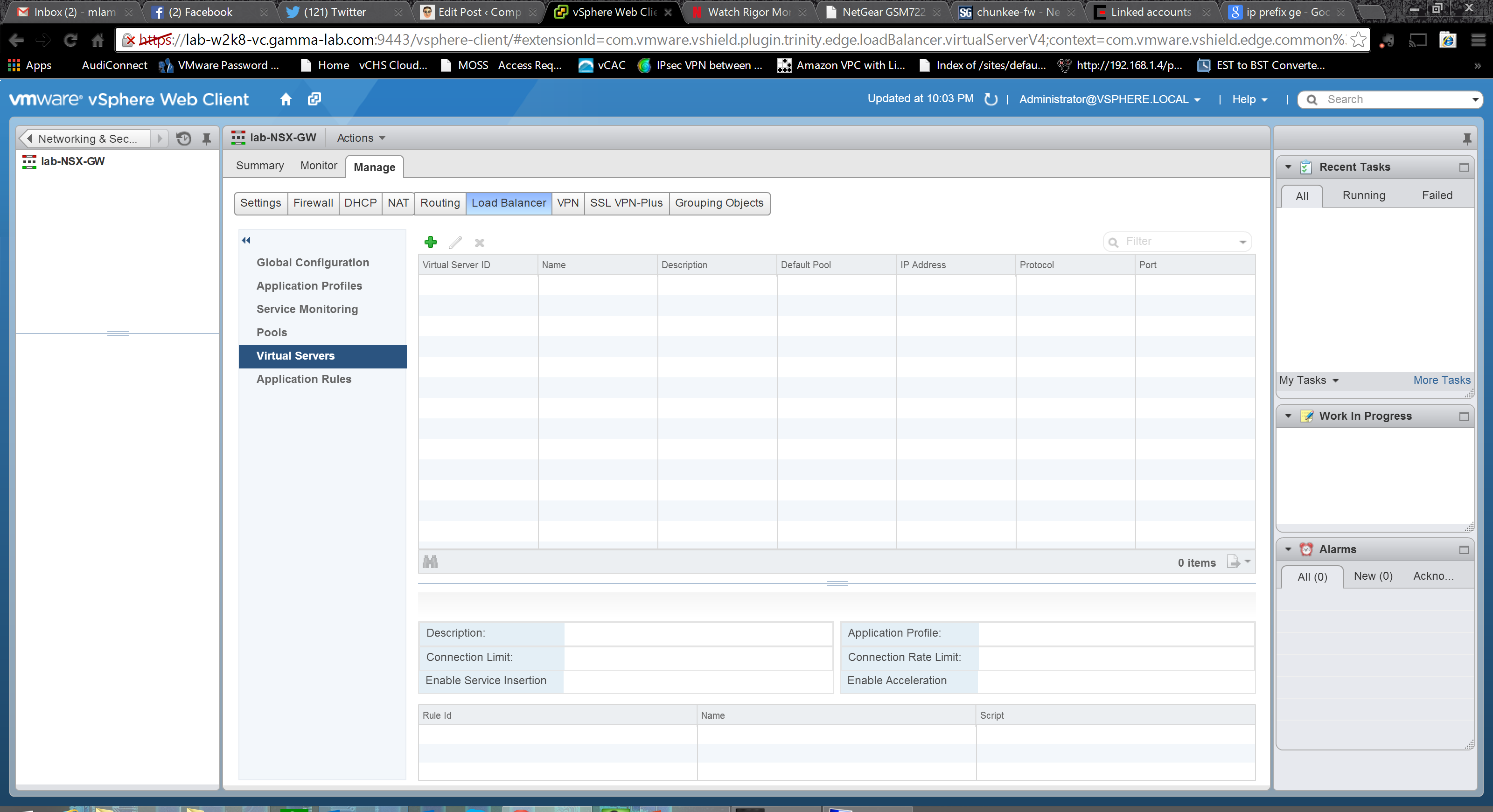
Phew. The routing configuration was intense! In an upcoming entry I plan to talk through various use cases that were once sealed off which NSX can unlock and the key to many of those is in the power of these routing capabilities. For now though, let’s move on to the Load Balancer configuration. Up top are the basic service controls plus options for logging, “Acceleration”. and “Service Insertion”. These last two require some explanation. “Acceleration” refers to the load balancing engine that will be activated in the appliance. Toggling this option switches between the faster Layer 4 engine (which obviously makes decisions based on TCP connection state) and the slower, but far more flexible, Layer 7 engine which enabled the ability to make decisions at the application layer. Obviously the right choice here is completely dependent on use case. “Service Insertion” allows the Load Balancer to integrate with third party appliance solutions:
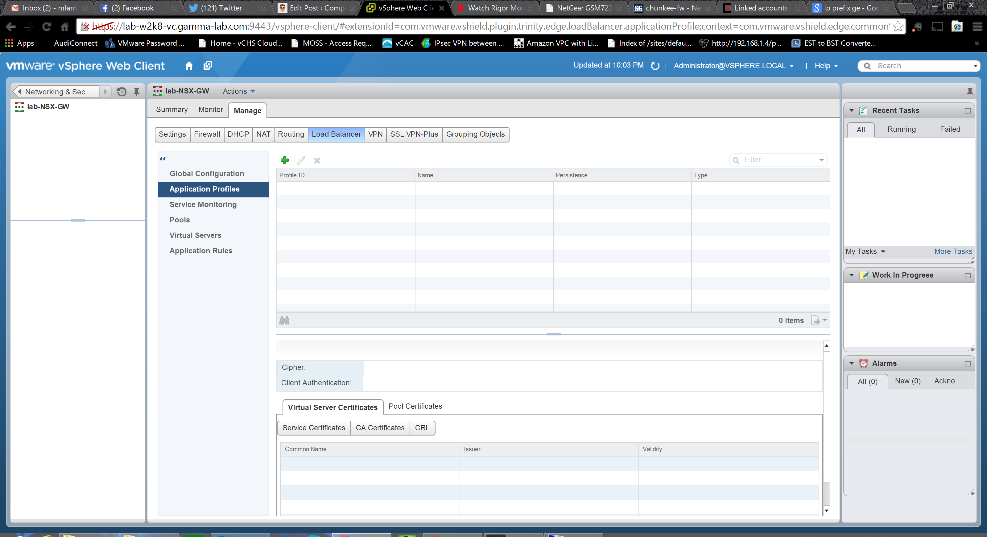
The next configuration group is “Application Profiles” which is where the L7 and L4 rules engines are configured. The bottom pane allows certificate configuration. Absolutely vital when working at the application layer where much traffic will be SSL/TLS:
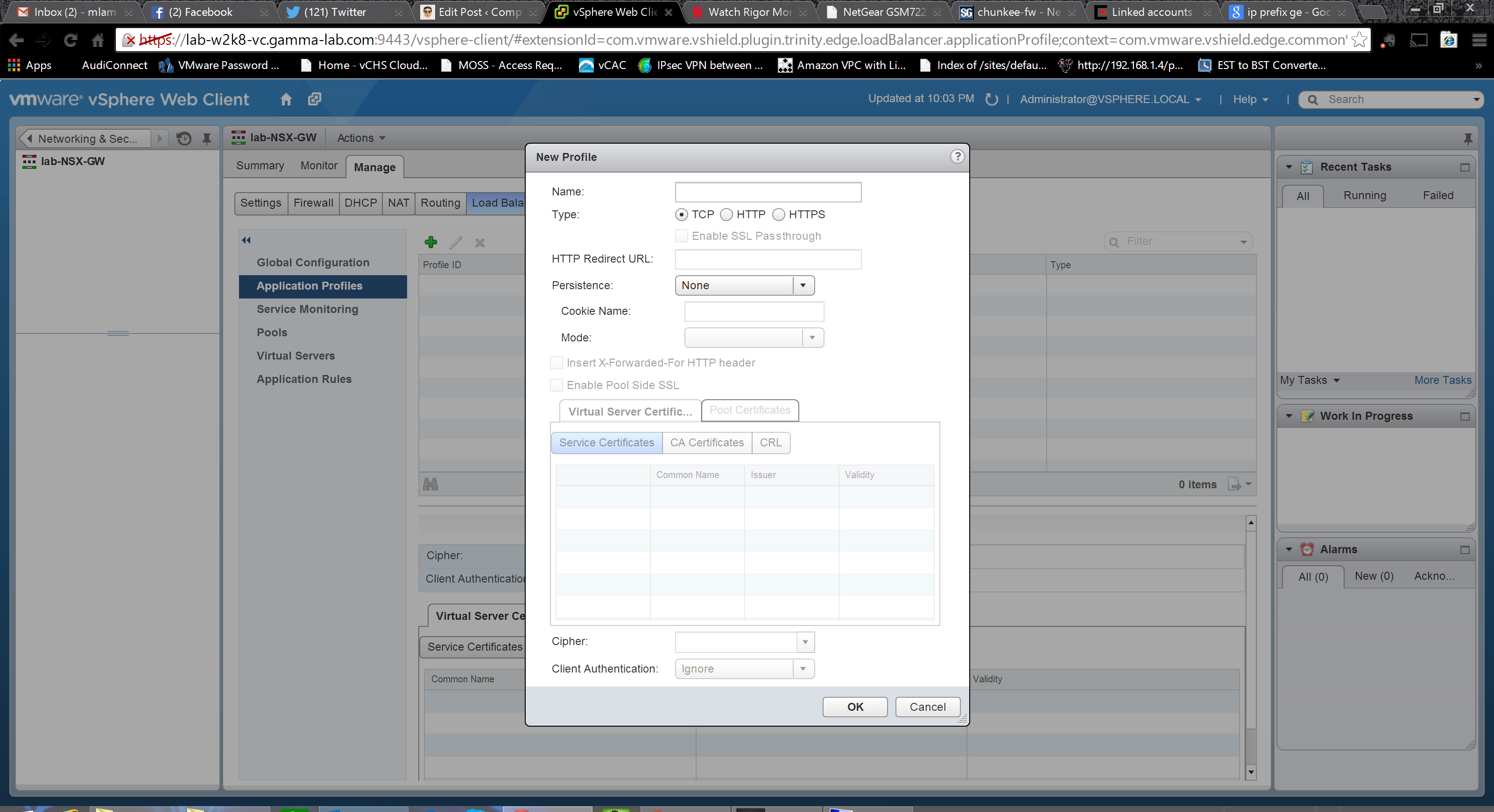
Fantastic options here for defining an Application Profile. Protocol obviously; TCP for L4, HTTP and HTTPS for L7. HTTP redirect is fully supported and a URL can be entered here. The ability to determine pathing and redirect via URL is critical for an application focused load balancer. Persistence and persistence mode can be set and a cookie name provided for cookie based persistence. In addition to these options, there is a toggle for enabling an “X-Forward-for-HTTP” flag into the forwarded header. This option is for support of proxy environments. The field is set to the actual originating IP so the load balancer can make decisions based on true source if desired. Without this field, in a proxy environment, the IP of the proxy will be seen as the source. Finally, comprehensive configuration for certificate assignment, auth method and cipher can be set here as well:
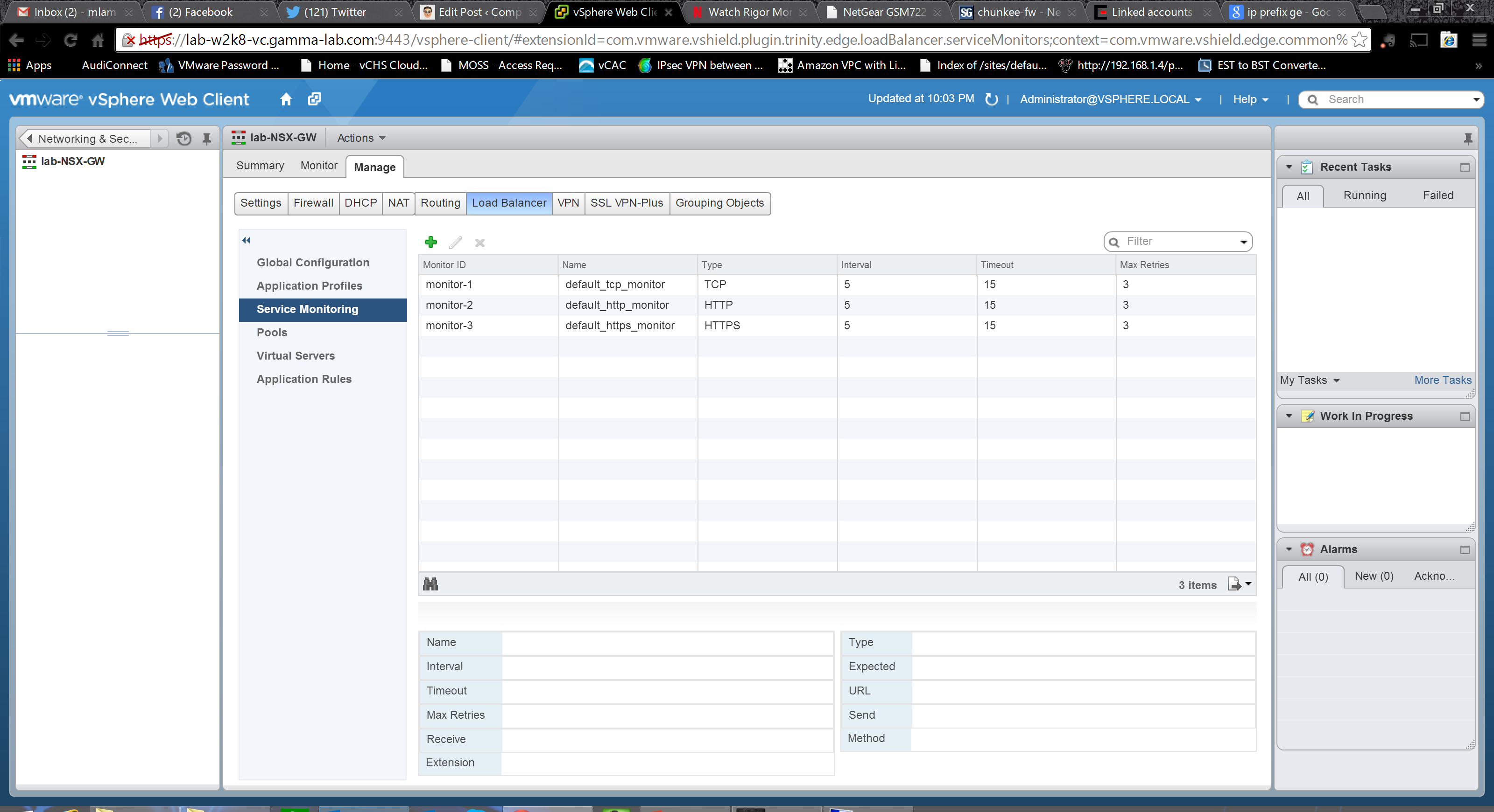
Application Profiles now created, we can move on to the Service Monitoring configuration. Here we can create monitors based on protocol and set timing intervals to govern load balancer listening behavior:
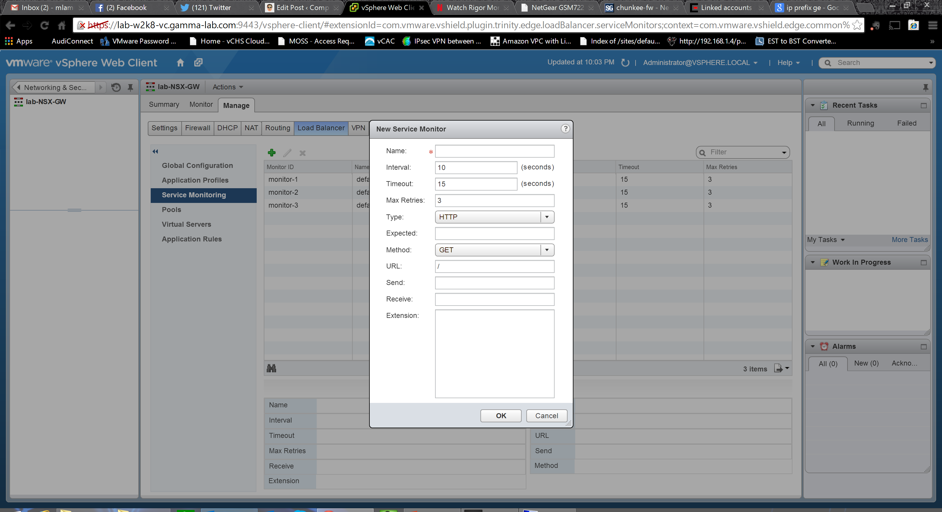
An example of creating a Layer 7 service monitor. HTTP method can be set as well as a specific URL to watch. In the “Expect” field we enter the literal string that indicates a match in the status line of the HTTP response. Next we select the “Method” to be used to detect server status. URL is the URL to be used in the sample request. Next, if the method is set to POST, comes the data that should be sent to that URL. For “Receive” we enter the expected response. In the “Expect” field we enter the expected response. If it is not matched the monitor does not try to match the Receive content. Finally, in the option extension area, we can enter additional monitoring parameters as key/value pairs. These are predefined (example: warning=10 sets the load balancer to trigger a warning on the service endpoint if a response is not received within 10 seconds).
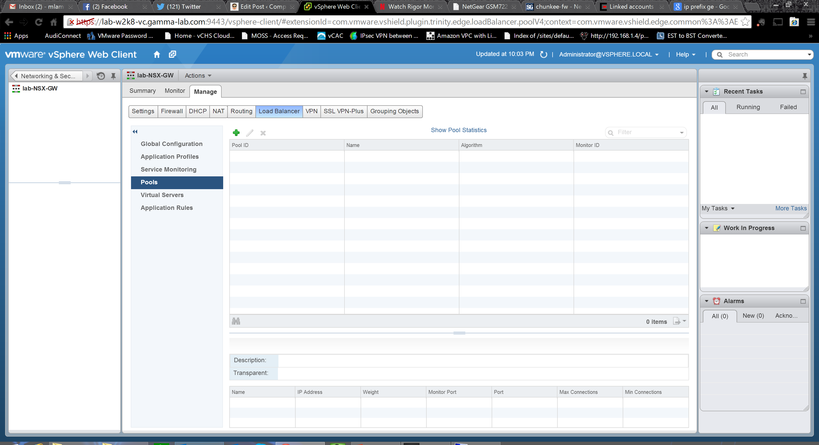
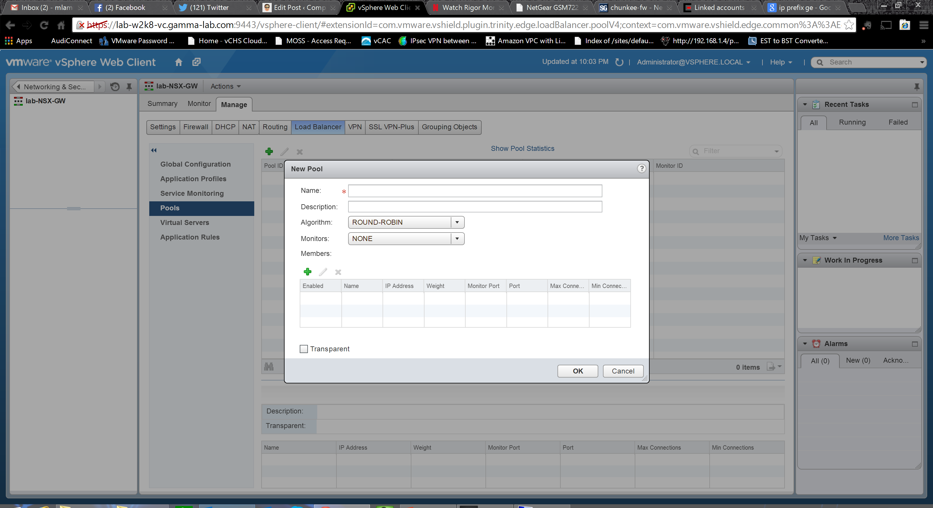
If you haven’t worked with advanced load balancers before, this may be a bit confusing but if you think through it it’s actually very straightforward. The point of a load balancer is to provide a single front end to a group of servers in scenarios where the application can “scale out”. So using a web server as an example, the name and IP address of the “server” are quite likely the logical server represented by the virtual IP of the load balancer. Behind the load balancer sit any number of actual web servers that handle the traffic. The load balancer, to do its work, needs to be able to do two things. First is decide how to distribute traffic, and second is to determine how many servers it is representing. The first one comes down to load balancing method selection. It might be a simple round robin which treats the known servers as a list, or it could be as complex as a hash on the originating IP which matches clients to servers based on layer 3 network associations. Server members and health similarly can be accomplished by a number of methods. The service monitor capability discussed above represents one of the more advanced ones. In this case the load balancer will literally have a layer 7 relationship with its member servers and use a URL connect / URL response to determine if the servers are alive:

Phew! That’s a ton of options and a really broad range of capabilities! This is a good place to break for now. Next up we will create a logical router!
